In this topic, you study Chopper (DC to DC converter) – Definition & Theory.
The DC to DC converter is also called as a chopper or a switched mode regulator. A DC chopper is an electrical circuit, that converts a fixed DC voltage to variable DC voltage.
DC to DC converter Block Diagram
The block diagram of a DC to DC converter is shown in Fig. 1. A fixed pure dc voltage is applied at the input of this converter and a variable dc voltage is obtained at its output. The input dc voltage can be obtained by rectifying and filtering the ac mains voltage or by using a battery bank.
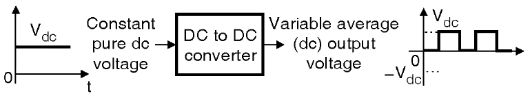
Fig. 1: DC to DC converter (chopper).
DC to DC converter Circuit Diagram
The circuit diagram of a DC-DC converter is shown in Fig. 2. The average output voltage is controlled by varying the conduction time of the transistor Q. If T is the chopping period, then T0 = DT where D is called as duty cycle of the chopper. The average output voltage is given by
V0 = D × VS
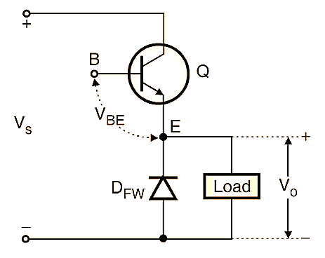
Fig. 2: DC to DC converter circuit diagram.
The waveforms of a DC-DC converter are shown in Fig. 3. The average output voltage of a chopper can be changed by changing either the duty cycle or the frequency of the output rectangular waveform (Fig. 3).
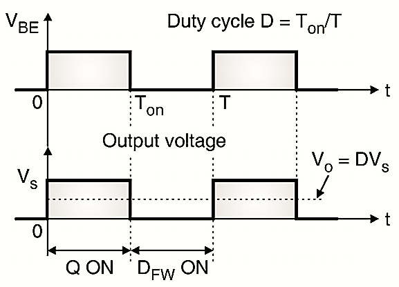
Fig. 3: DC to DC converter waveforms.
Applications of DC to DC converter
The DC to DC converters are used in SMPS, battery chargers, battery operated electric vehicles etc. A DC chopper is used to control the speed to DC motor from a battery or DC supply.