In this topic, you study DC Chopper – Diagram, Working, Advantages, Applications & Classification.
In a.c. applications, the transformer serves to convert electric a.c. power efficiently from one voltage level to another. The transformer is used as a.c. to a.c. converter. In d.c. applications also, many times we need to convert electric d.c. power efficiently from one voltage level to another, static d.c. to d.c. converters by stepping up or stepping down the d.c. voltage source to achieve the similar function in d.c. applications. This function may be performed by using switching semiconductor devices such as BJT or SCR. A chopper is a static device (switch) used to convert variable d.c. voltage from a source of constant d.c. voltage. A chopper can be considered as a d.c. transformer.
Advantages of DC Chopper
The advantages of chopper are as given below:
- It has greater efficiency.
- It has faster response.
- It requires less maintenance
- It has compact size.
- It has smooth control.
- It is cheap. Its cost is lower than motor-generator sets.
Applications of DC Chopper
The applications of chopper are as given below :
- It is used in battery-operated vehicles for fast dynamic response.
- It is used for control of a.c. series motors in traction systems.
- It is used for control of a large number of d.c. motors.
- It can be used to control the speed of (wound rotor) induction motor .
- It can be used in switched mode power supply (SMPS) regulators.
- it is used in subway cars to reduce the tunnel heating.
- It is used in trolley cars, marine hoists, mine haulges and forklift trucks.
- It can be used in electric automobiles.
Basic Chopper Circuit details
Fig. 1 (a) shows the basic circuit of a chopper and its associated waveforms shown in Figure 1 (b). The solid-state (switching) devices such as BJT, SCR or GTO can be used as a series switch S. Usually the load is inductive, therefore, a freewheeling diode D is connected across the inductive load for free circulation of load current when the switching device is turned OFF. If the load is resistive, then there is the necessity of freewheeling diode D.
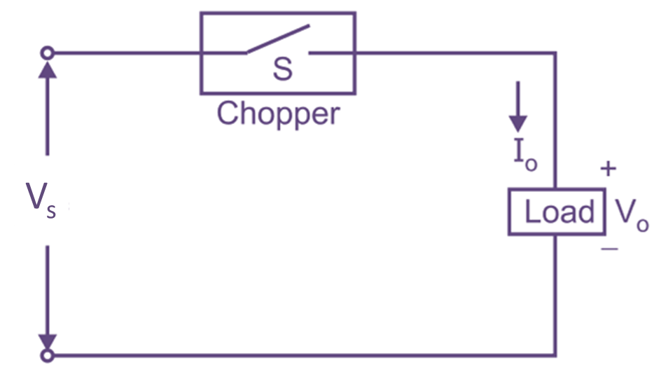
(a)
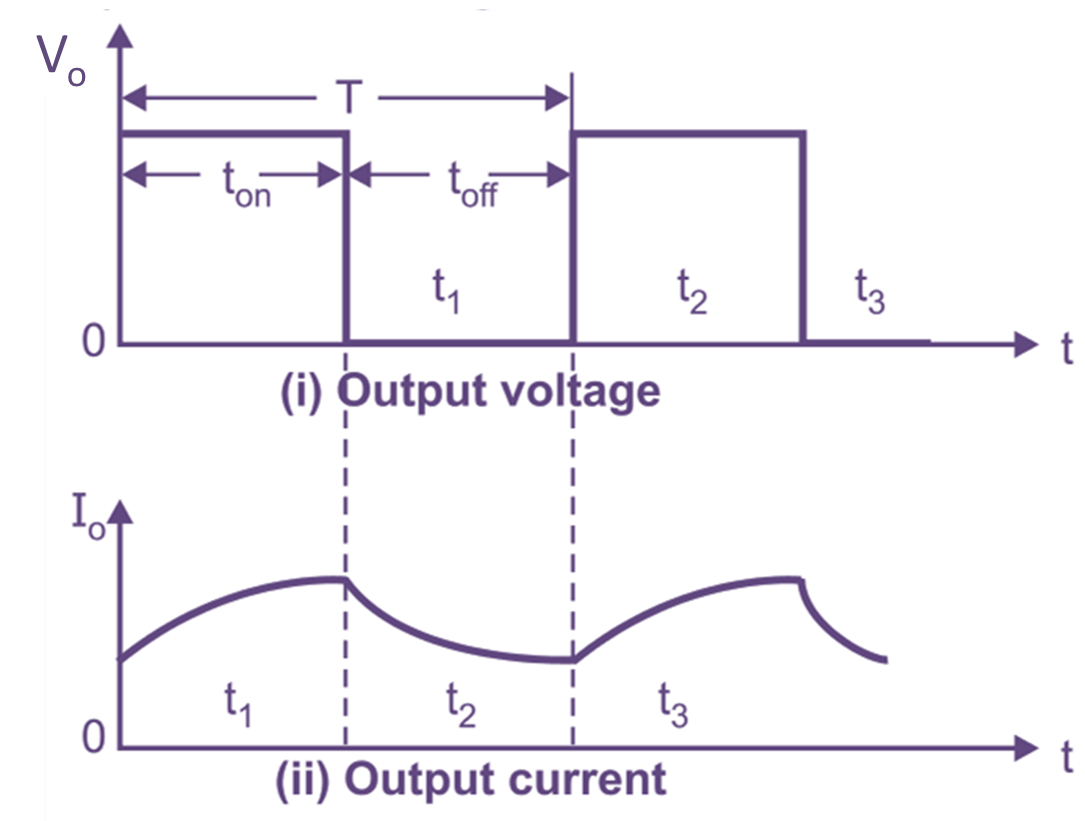
(b)
Fig.1: DC Chopper configuration
Basic principle of DC Chopper
Chopper is basically a series switch which is turned ON and OFF at high frequency to get square pulse train. Average voltage can be controlled by varying the ratio of turn-ON and turn-OFF periods. At the beginning of ON period ton, the switch S is turned ON. During the period, the load voltage Vo, is equal to supply voltage Vs and the load current rises exponentially. When the switch S is turned OFF, the load current circulates through freewheeling diode D and load current falls to zero.
. The average voltage is given by
\[{{\text{V}}_{\text{o}}}=\frac{\text{1}}{\text{T}}\int\limits_{\text{0}}^{{{\text{t}}_{\text{on}}}}{{{\text{V}}_{\text{s}}}}\cdot \text{dt}\]
\[{{\text{V}}_{\text{o}}}=\left( \frac{{{\text{t}}_{\text{on}}}}{\text{T}} \right)\cdot {{\text{V}}_{\text{s}}}\]
\[\text{since, }\frac{{{\text{t}}_{\text{on}}}}{\text{T}}=\text{ }\!\!\alpha\!\!\text{ }\]
\[{{\text{V}}_{\text{o}}}=\text{ }\!\!\alpha\!\!\text{ }\cdot {{\text{V}}_{\text{s}}}\]
where, T = Time period of chopping
$\text{ }\!\!\alpha\!\!\text{ }$ = Duly cycle of a pulse
By controlling the duty cycle $\text{ }\!\!\alpha\!\!\text{ }$, the load voltage can be controlled from 0 to Vs.
Classification of Chopper
D.C. choppers can be broadly classified as under:
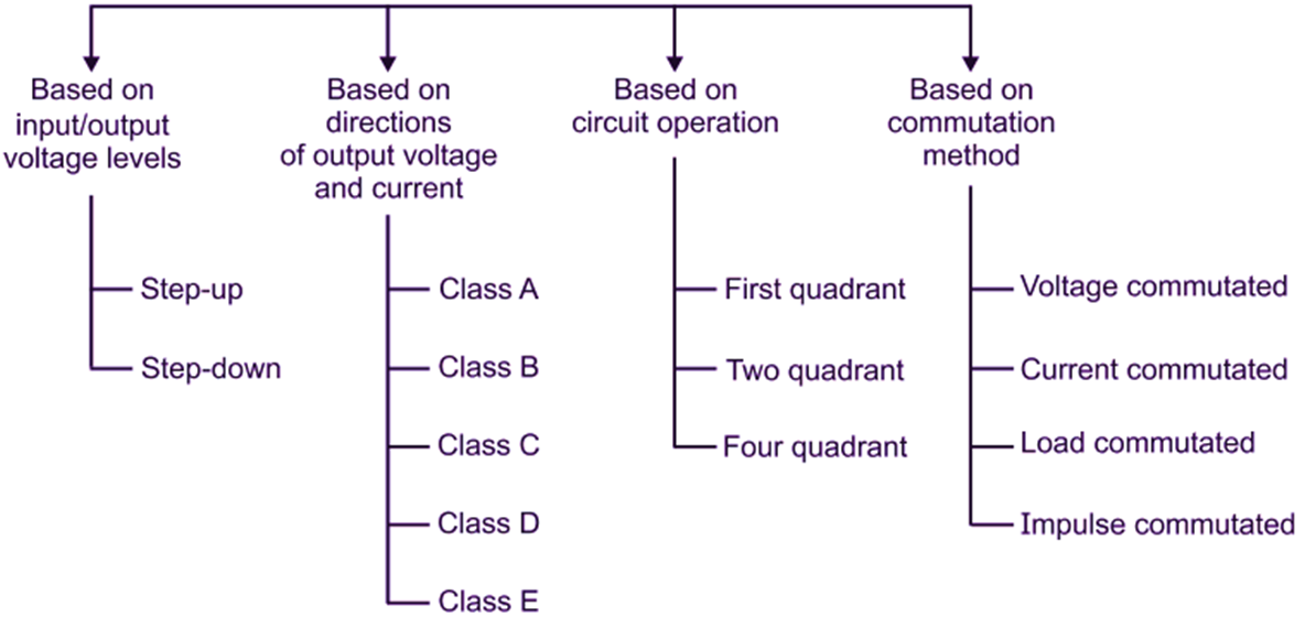
- Based on the input/output voltage levels:
- Step-down chopper
- Step-up chopper
- Based on directions of the output voltage and current:
- Class A (type A) chopper
- Class B (type B) chopper
- Class C (type C) chopper
- Class D (type D) chopper
- Class E (type E) chopper.
- Based on circuit operation:
- First—quadrant chopper
- Two-quadrant chopper
- Four-quadrant chopper
- Based on commutation methods:
- Voltage-commutated choppers.
- Current-commutated choppers.
- Load-commutated choppers.
- Impulse commutated choppers.