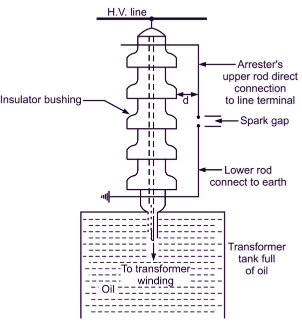
Rod Gap Arrester is generally located across the bushings of transformer and generally used as back up protection in case of main arresters.
Construction of Rod Gap Arrester
As shown in Fig. 1 the arrester is in the form of bend-rods having spark-gap between the two. The upper rod is connected to the line electrically and the lower one is connected to the earth to carry away surge current.

Fig. 1: Rod Gap Arrester
Dimensions of Rod Gap Arrester
1.5 cm rods bend at 90° as shown, distance ‘d’ between gap and bushing outside, face > 1/3 gap length to avoid reaching of arc to the bushing body. The gap length is so adjusted that breakdown should occur at 0.8 of spark overvoltage.
Working of Rod Gap Arrester
Under normal voltage conditions the gap acts as a air insulation and non-conducting and the line voltage is ineffective to make the gap conducting.
Now when the voltage increases so suddenly due to surge on the line, this surge voltage breaks the gap between the rods and spark over (arc) is produced. Surge current passes from the line to spark-gap to second rod and finally to the earth within a very short time and the equipment is protected. After the surge the gap as a insulator under normal voltage of the line.
Drawbacks and Limitations of Rod Gap Arrester
- It is expected that after the surge is over arc shall blow off but there is a chance of remaining it in the gap due to the normal voltage also. This is due to absence of non-linear resistance in its circuit. This may lead to short circuit.
- If not properly designed the rods may bend, melt, damage due to over heating caused by the arc.
- Rain water, humidity, temperatures may affect the gap and the arrester may not give good service.
- The polarity of the surge may also affect the performance of the arrester. So its uses are limited.
Applications of Rod Gap Arrester
- Transformer protection.
- Back-up protection with main arresters.