Overcurrent relays are used for protecting the equipment by over-currents. Over currents may cause the break in insulation if temperature exceeds the limits for which the insulation is designed. For wide varieties, these relays are used which are listed below
Over-current protection: Thermal relays.
Low voltage distribution system: HRC fuse, drop out fuse.
For instantaneous over-current protection: Moving iron type, moving coil type, attracted armature type relays.
For inverse time characteristics: Electromagnetic induction relay, permanent magnet moving coil type or static relay.
Directional overcurrent protection: Double actuating quantity induction relay with the directional feature.
Induction Type OverCurrent Relays (Non-Directional)
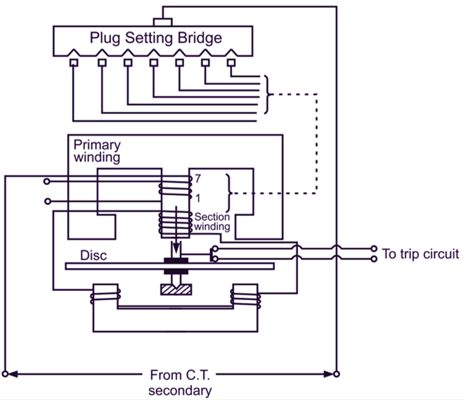
Fig. 1: Induction Type Overcurrent relay
Construction: The relay works on induction principle. Actuating quantity is current (from CT secondary). The primary winding is connected to the secondary of C.T. in the line to be protected as shown in Fig. 1. An aluminium disc is pivoted which moves freely between two electromagnets. The primary is tapped (1….7). The tappings are connected to plug setting bridge so that number of active turns on relay can be changed and desired current setting can be obtained. Secondary winding is connected to lower magnet by series connection. Due to induction principle emf is induced in secondary due to current in primary. The torque exerted on the disc is due to interaction of eddy currents in the disc and flux produced by upper and lower magnets.
The two fluxes have phase displacement. The spindle carries moving contact which bridges the two fixed contacts which are connected to trip circuit. The moving contact move through a preset angle. By adjusting this angle (from 0° to 360°) travel of moving contact can be adjusted and hence time setting is also possible. Restraining torque is provided with the help of spring.
Operation: Torque is produced on aluminium disc due to interaction of eddy current in the disc and two fluxes produced by upper and lower magnet. Under normal working condition restraining torque is greater than driving torque which is produced by relay coil current. So aluminium disc does not rotate. If current exceeds preset value, driving torque is greater than restraining torque. And disc rotates through preset angle causing bridging of trip circuit contacts. The trip circuit operates causing the opening of C.B., fault is cleared.
Static OverCurrent Relay
The overcurrent relays are used to detect faults in the distribution system. If the line is fed from both ends i.e. ring main system, these relays are used along with directional relays. These static overcurrent relays have the following advantages over electromagnetic relays
- These consume very less power. These are connected to CT secondary. So CT burden is very less, hence smaller capacity CTs can be used.
- Size is smaller, pannel ¡s compact.
- Automatic reclosing for circuit breakers can be provided.
- Less maintenance.
- Long life.
- Better accuracy.
Block diagram of Static OverCurrent Relay
The block diagram of static overcurrent relay is shown in Fig. 2. The CT steps down the current which is fed to the rectifier unit. The rectifier converts AC to DC. The output of rectifier is fed to overload detector. It compares the signal with reference value, if overload occurs signal is passed to the timing circuit. Timing circuit consists of RC components. When voltage across the capacitor reaches the value of triggering level, the level detector circuit detects it and sends the triggering signal to the tripling circuit. The tripping circuit causes tripping of relay.
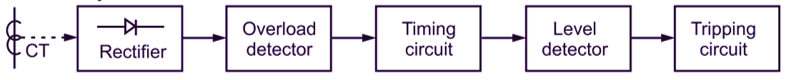
Fig. 2: Block diagram of static overcurrent relay
Overcurrent Relay Applications
All these relays are aimed on over-current principle. In following electrical equipment the overcurrent relays are used
Transformer protection
Overcurrent relay in addition to differential relay to take care of through faults.
Feeder line protection
- Differential overcurrent relay.
- Instantaneous overcurrent relays.
- Inverse time overcurrent relay.
Motor protection
- For small capacity motors: HRC fuse, thermal relays.
- For big capacity motors: Inverse time and instantaneous overcurrent protection.