In this topic, you study Single Phase Energy Meter – Working, Construction & Diagram.
A single phase energy meter is used for measuring the power consumption in kilowatt-hours (kWh) of a domestic or industrial electrical installation.
Construction of Single Phase Energy Meter
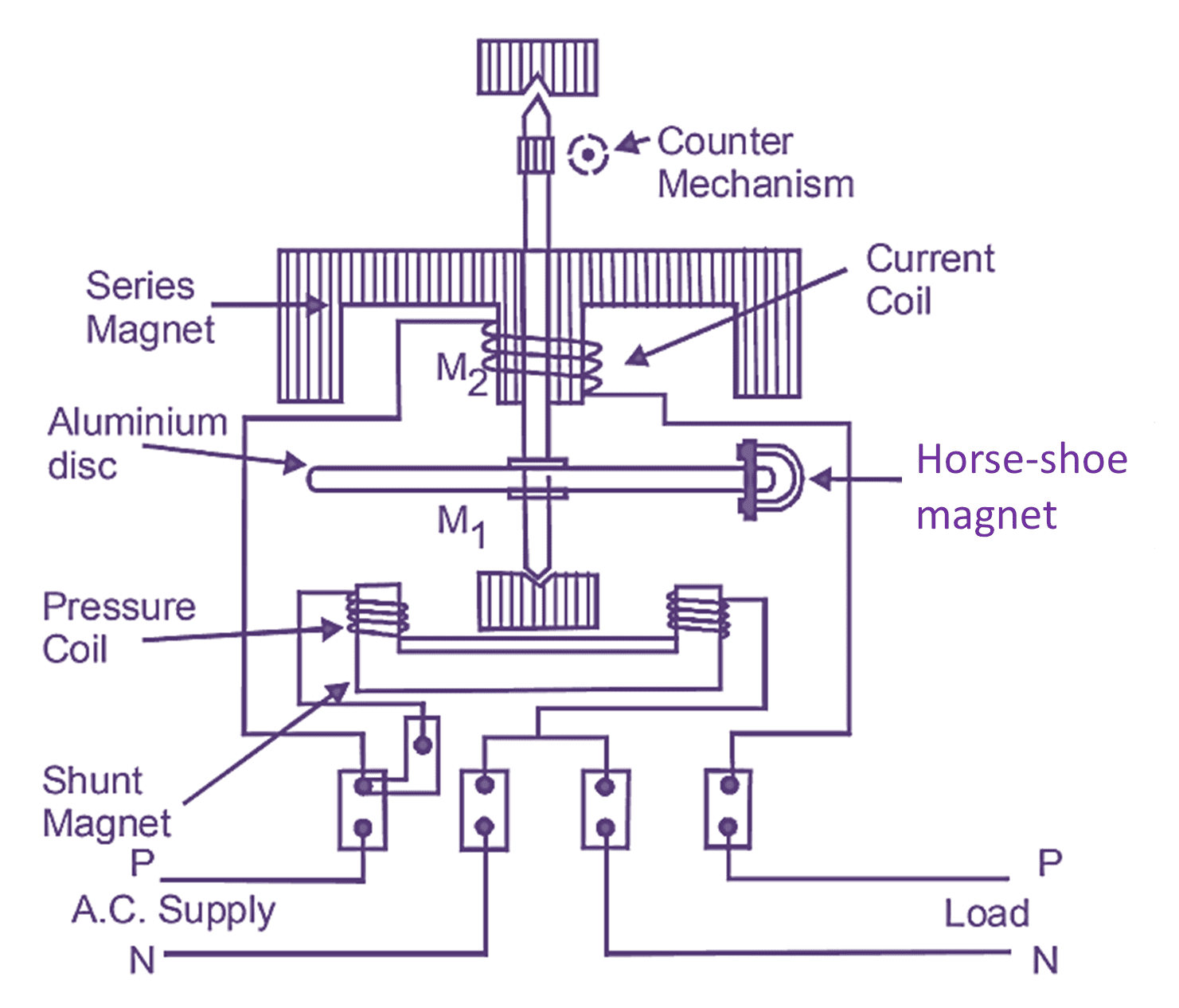
Fig. 1: Single Phase Energy Meter.
A single phase energy meter is a sort of induction type watt-hour meter. It consists of two electromagnets. One magnet is called the shunt magnet Ml which is mounted with a pressure coil. The pressure coil is a long coil made of fine copper wire which is connected across the supply line. Another magnet is called the series magnet M2 which is mounted with current coil. The current coil is a short coil made of thick copper wire which is connected in series with the load. There is a round aluminium disc which is placed between two magnets and it is mounted on a spindle. The spindle rests on two pivots. A horse-shoe magnet is placed on one side of the disc to provide damping, as shown in Fig. 1.
Working of Single Phase Energy Meter
When the meter is connected to the supply line and the load, then both the coils produce their magnetic fields. The field produced by the current coil is directly proportional to the magnitude of current flowing through it (or through the load, since it is connected in series with the load). The field produced by the pressure coil depends on the voltage across it. Both the fluxes produce eddy currents in the disc. Thus, we have two fluxes and two eddy currents and therefore two driving torques resultant produced on the disc.
The damping torque is produced by the permanent magnet. Shading rings are mounted on the shunt magnet for the correction in power factor of the meter. The rotational speed of the disc is counted by a counting mechanism which may be of any one of the following types:
- Cyclo dial
- Clock dial
- Number dial
1. Cyclo Dial: This system consists of many round discs each marked with 0 to 9 digits on its periphery. All the discs are connected with gears to each other. The collective reading of all the discs shows kWh.
2. Clock System: This system is identical to a clock. It consists of 6 dials each marked with 0 to 9 digits on its periphery. The dials show thousand, hundred, ten, unit, 1/10th and 1/100th of a unit (kWh). The last two dials are of red color.
3. Number Dial: This system consists of seven geared rings each marked with 0 to 9 digits on its rim. All the rings together show the reading in kWh.