In this topic, you study Energy Meter – Working, Construction & Diagram.
Energy Meter is used for measuring the power consumption in kWh of a domestic or industrial electrical installation.
The energy is the total power delivered or consumed during a time interval. The energy is product of power and time (E = P × t). Its unit is joule or watt second, which is equal to 1 watt over an interval of 1 second. If time is taken in hour. the energy is then expressed in watt hour (Wh). In many cases, wh is a small unit than kilowatt hour (kWh) is used and 1 kWh = 1 kW × 1 hr = 1000 W × 1 hr. = 1000 Wh. The “Kilo watt hour” is also called as a “Board of trade (B.O.T)” unit in commercial sector. The energymeter therefore is an instrument which can measure quantity of energy supplied to a circuit in a given time. The instrument is also called as “Kwh meter”.
Working Principle of Energy Meter
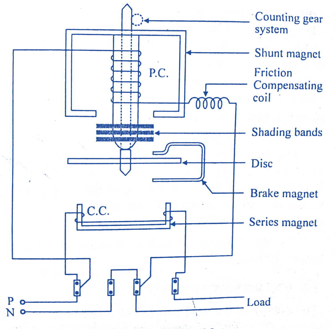
Fig. 1. Induction Type EnergyMeter.
The basic principle of induction energy meter is electromagnetic induction. A thin disc of aluminium (or copper) is pivoted between the two Shunt and Series magnets and cuts the fluxes of both the magnets (Fig. 1). Hence two eddy currents are induced in the disc. The driving torque on the disc is produced as a result of interaction of the two inducing fluxes. A “shading banc can be adjusted to get the resultant flux in shunt magnet exactly lagging by 90 to the applied voltage. A “Brake magnet” produces a controlling torque on the disc, which has no pointer, as an energy meter is an integrating instrument and the disc has to rotate continuously so long the meter remains connected in the circuit.
Construction of Energy Meter
The single phase induction type energymeter has the following important parts :
- Driving system,
- Moving system,
- Braking system,
- Recording system.
Driving System
The driving system is made of two electromagnets.
Series magnet
It consists of a no. of V-shaped laminations Of silicon steel forming a core. A coil of thick wire and of few turns is wound on this magnet and is connected in series with the load. It carries line current and therefore called “current coil” (C C). This magnet produces a magnetic field proportional to and in phase with the line current.
Shunt magnet
It consists of numbers of M shaped laminations of silicon steel assembled together as a core. A coil of thin wire large number of turns is wound on its central limb. The coil is connected across the load and carries a current proportional to the supply voltage and therefore called a “potential coil” (PC).
In order to obtain the driving torque on the disc, current in the P.C. must lag supply voltage exactly by 90°. For this one or more shading bands are provided on the central limb of the shunt magnet. The shading band has to be adjusted to the exact 90° phase difference. Since resistance of the shading band coil is bly small as compared to its inductance, therefore current in the band lags the voltage approximately by 90. Thus the shunt magnet produces a magnetic proportional to the supply voltage. The frictional errors may be adjusted by the “Friction compensating coil’ placed in the potential circuit of the meter. Sometimes “shading coil” is placed in the limb of the shunt magnet for this purpose.
Moving System
It consists of a light aluminium disc mounted on a spindle and positioned in the gap in between the two magnets. This disc rotates continuously under the driving torque produced by the two magnets. Note that there is no controlling
Braking System
A permanent magnet called “Drake magnet” near the edge of the disc comprises braking system. When disc rotates in the magnetic field of the break disc cuts this field and (and thus eddy currents) is induced in the disc. The direction of eddy currents is opposite to the direction of rotation of the disc (lez’s law) and thus it controls the rotation. As the eddy currents are proportional to the disc speed, so the braking torque is also proportional to the disc speed. The amount of Braking torque can be adjusted by adjusting the position of the braking magnet. If the braking magnet is moved towards the centre of the disc the flux cut by the disc is reduced and so reduces the induced currents and the braking torque. This will increase the speed of the disc. Reverse happens if the break magnet is moved outward from the disc.
Recording System
The function of recording system is to register/count the no. of revolutions made by the disc. By using a train of gears on the disc spindle, 5 to 6 pointers are driven. These pointers rotate on dials which are marked with ten equal divisions. The Fig. 2. shows a pointer type recording and Fig. 3. shows a cyclometer type recording. Thus we can see that the construction of 1 phase induction energy meter is similar to a 1 ph shaded band Induction motor. The disc may be taken as the rotor of the motor. The Fig. 4. shows another view of 1 phase energymeter.
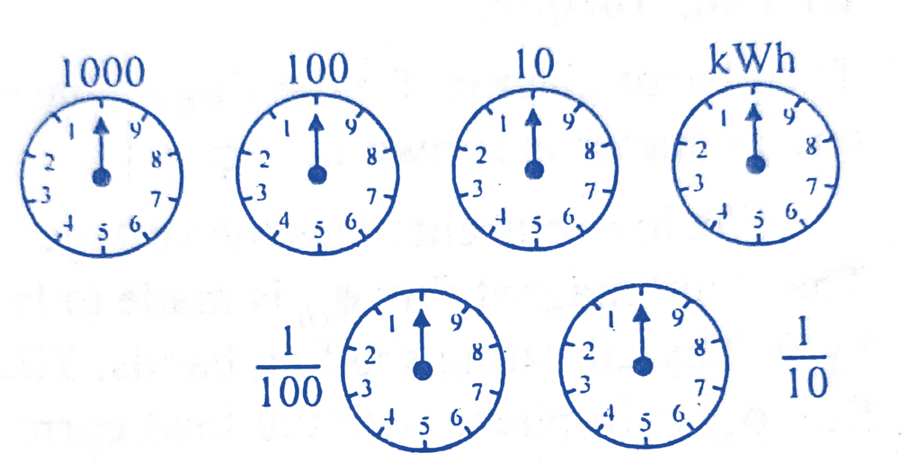
Fig. 2. Pointer Type Recording.
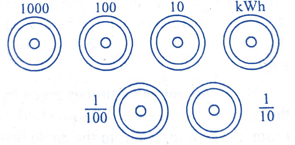
Fig. 3. Cyclometer Type Recording.
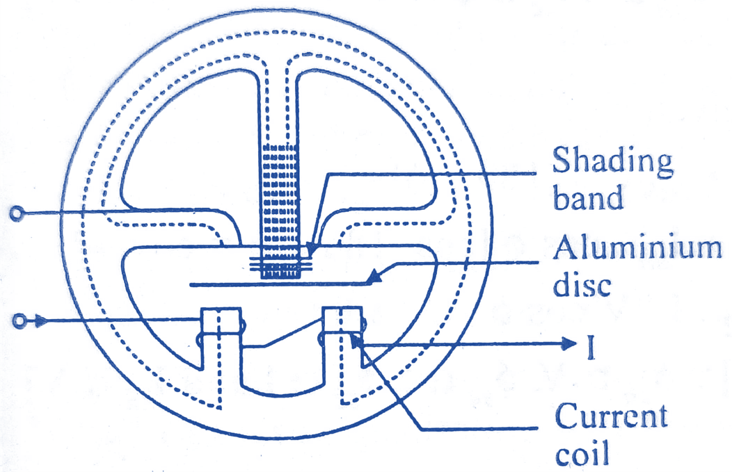
Fig. 4. A View of Energy Meter.
Lag Adjustment In Energy Meters
The energy meter will register correct energy only if the shunt magnet flux lags the voltage exactly by 90°. This requires that the pressure coil should be highly inductive. If the angle is not 90°, it is to be adjusted by shading bands provided on the central limb of the shunt magnet. This is known as lag adjustment. Sometimes it is also called as “low power factor”/Quadrature or Reductive load adjustment. The adjustment is done by moving the shading bands (Fig. 5.) along the axis of the central limit:
- As the bands are moved up the limb they embrace more flux. This results in greater induced emf and current produced by the bands therefore, the value of “lag” angle increases.
- When the shading bands are moved down. The limb induced emf and current decreases and the “lag angle” also decreases. The adjustment is done in such a way that the angle of lag is exactly 90 i.e., is brought exact in quadrature with the voltage.
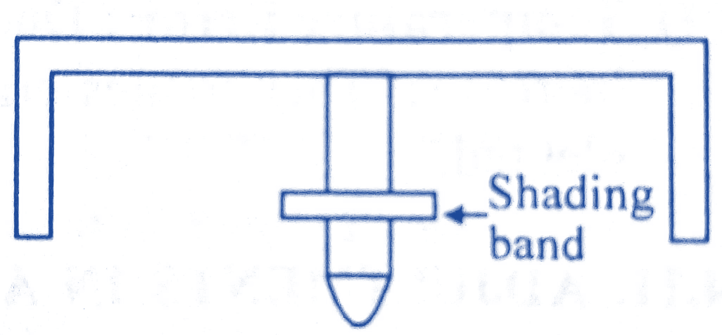
Fig. 5. Lag Adjustment
Errors in Induction Type Energy Meter
Few errors which are common in induction energymeter are described below :
Phase Error
Normally the flux due to shunt magnet does not lag the supply voltage exactly by 90°. The reason being that the shunt coil has some resistance. Due to this, the angle of phase is less then 90°, as a result, the torque on the disc is not zero at zero power factor. It is adjusted by adjusting the position of shading bands on the central limb of the shunt magnet.
Speed Error
If the disc moves faster or slower, it is called as “speed error”. If the disc moves faster it will give a higher reading and viceversa. This error may be compensated by moving the brake magnet towards or away the centre of the disc. Moving the brake magnet towards centre of the disc reduces braking torque, thus increasing the disc speed and vice-versa.
Creeping
This is the error, when the disc makes slow motion even at no load. For compensating error. two holes are drilled on the diameter of the disc.
Temperature Error
Due to temperature error, resistance of the disc and coils increases. This creates error. This error however is very small and can be neglected.
Adjustments in the Energymeter
Some adjustments are done in the energymeter, so that the errors remain within limits. These adjustments are given below :
Full load unity power factor (P.F.) adjustment
The pressure coil is connected across the rated supply voltage. Rated full load current at unity power factor is also passed. The position of the brake magnet is adjusted, so that the disc revolves at correct speed.
Lag adjustment (low P.F. adjustment)
- The pressure coil is connected across rated supply voltage and rated full load current is passed through the current coil at 0.5 P.F. lagging. The shading band on the shunt magnet is so adjusted that the disc moves at a correct speed.
- With rated supply voltage, rated full load current and unity P.F. the speed of the disc is checked. Now full load unity P.F. and lag (low P.F.) adjustments are repeated till the desired accuracy is obtained for both the conditions
Load adjustment
- Light load adjustment: Rated supply voltage is applied across the pressure coil and a very low (5
- Full load and light load adjustments at unity P.F. are repeated till correct speed is obtained at both the loads.
- Re-check the performance of the meter at 0.5 P.E. (logging),
Creep adjustment
The pressure coil is excited at 110 percent or the rated voltage with zero load current. The meter should not “creep”
Frictional adjustment
The frictional error in the induction type energymeter is compensated by placing shading (short circuiting) bands at the side limbs of the shunt magnet.