It is widely used for torque measurement. Therefore, it is also called as strain gauge torsion dynamometer. Fig. 1 shows a strain gauge transmission dynamometer configured with a strain gauge Wheatstone bridge circuit.
Construction of Strain Gauge Torsion Dynamometer
Four bonded-wire strain gauges are mounted at an angle of 45° with respect to the axis of rotation. They are placed in pairs, but diametrically opposite. The gauges are accurately placed, such that, the system is temperature compensated and insensitive to bending, thrust or pull effects. Any change in the gauge circuit then results only from torsional deflection.
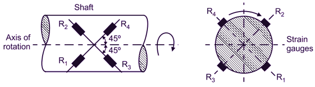
Fig. 1: Strain Gauge Transmission Dynamometer
Working of Strain Gauge Torsion Dynamometer
When the shaft is under torsion, gauges 1 and 4 will elongate as a result of the tensile component on one diagonal axis. Whereas, gauges 2 and 3 will contract due to compressive component on the other diagonal axis. These principal strains (tensile and compressive) are measured and hence, torque on shaft is calculated. Further, these strain gauges are connected to Wheatstone’s bridge circuit. Galvanometer shows the output of Wheatstone’s bridge, which is proportional to torsion and hence, to applied torque on shaft.
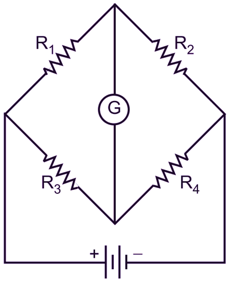
Fig. 1: Wheatstone’s Bridge Circuit for Strain Gauge Transmission Dynamometer
Advantages of Strain Gauge Torsion Dynamometer
- Fully temperature compensated.
- Provides automatic compensation for bending and axial loads.
- Gives the maximum sensitivity for a given torque.
- Gives an instantaneous result.
Limitations of Strain Gauge Torsion Dynamometer
- Expensive.
- Initial setting needs skilled operator.
- Initial setting is time consuming.