Wire type bonded strain gauge consists of a thin sheet of insulating material such as, Paper, Bakelite or Teflon. Generally, strain gauge wire has a diameter 0.025 m, It has uniform cross-sectional area throughout its length.
Construction of Wire Strain Gauge
Materials used for metallic wire are,
- Constantan (Copper-Nickel alloy),
- Nichrome V (Nickel-Chrome alloy) etc.
This strain gauge wire is cemented between two thin sheets made-up of insulating material (one at bottom and other at top), in such a way that, spreading of wire permits a uniform distribution of stress. At the time, precaution is taken to protect the strain gauge wire from any mechanical damage. Refer Fig. 1. Two terminals of wire are taken out as connecting leads or terminal leads, which may be extended using copper wires. Such assembled strain gauge is bonded with an adhesive material to the structure under test. This permits a good transfer of strain from the structure under test to the strain gauge wire.
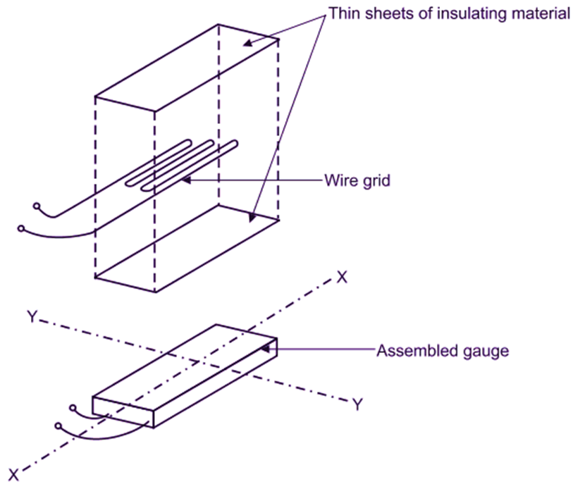
Fig. 1: Illustrative View of Wire Type Bonded Strain Gauges
Working of Wire Strain Gauge
Two terminal leads of strain gauge form one arm of Wheatstone’s bridge circuit. When quantity being measured is zero, the resistances of all arms are so adjusted that the galvanometer shows zero deflection (Figure 2). When the strain is applied, resistance of strain gauge wire changes causing unbalance in the bridge. The deflection shown by galvanometer is calibrated in terms of quantity being measured, which may be strain, stress, force, pressure, displacement, acceleration etc. This type of strain au e is used as load cell.
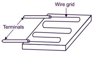
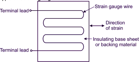
Fig. 2: Wire Type Bonded Strain Gauges