RVDT is used to sense the angular displacement. It is an inductive transducer, which converts angular displacement into an electrical signal. Here,
R = Rotary motion / Angular displacement
V = Variable inductance
D = Differential, which means output is difference of two secondary outputs
T = Transformer, because it functions as the former of primary and secondary windings.
Working principle of RVDT
Rotation of iron core (magnetic core/armature) is responsible for varying the differential voltage of two secondary windings of a transformer, which is a measure of angular displacement.
Construction of RVDT
RVDT consists of two secondary windings having equal number of turns, but wound in opposite direction of primary winding connected across single phase A.C. supply. A magnetic core or armature is placed in the air gap between primary and secondary windings. It is free to move in either direction depending on angular displacement of shaft.

Fig. 1: Illustrative View of RVDT
Working of RVDT
When single phase A.C. supply is given to the circuit, it produces magnetic flux, which completes its path through S1 and S2. While completing the path, the flux produced by primary winding is linked to number of conductors of secondary windings. Therefore, according to faraday’s law of emf, an emf is produced in secondary winding. As shown in Fig. 2, the output voltage of S1 is ES1 and that of S2 is ES2. To convert the output of S1 and S2 into single voltage signal, S1 and S2 are connected in series as shown in Fig. 2. Thus, the output of transducer will be the difference of two voltages i.e. differential output voltage. i.e. Eo = ES1 – ES2.
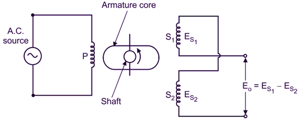
Fig. 2: RVDT
Various positions of Core and Corresponding Displacement Measurements:
When the core is at central position, the magnetic flux linking to both Sl and Sz is equal and hence, equal emfs are induced in S1 and S2. Thus, ES1 = ES2. Therefore,
Eo = ES1 – ES2 = 0
This position of core is called as normal (null) or zero position. It concludes that, output voltage is zero at null position.
When the core rotates anti-clockwise, then the flux linking to coil S1 increases and at the same time, the flux linking to coil Sa decreases. Hence, emf induced in coil S1 (ES1) is greater than that of S2 (ES2). As a result of which, output measured between secondary terminals is in phase with primary voltage.
When the core rotates clockwise, then the flux inking to coil S2 Increases and at the same time, the flux linking to coil S1 decreases. Hence, emf induced in coil S2 (ES2) is greater than that of S1 (ES1). As a result of which, output measured between secondary terminals is out of phase With primary voltage. Hence, output (ES1 – ES2) measured between two secondary terminals of RVDT is directly proportional to angular displacement of magnetic core.
Advantages of RVDT
- Infinite resolution and linear operation.
- Ability to measure clockwise as well as anti-clockwise angular displacement.
Disadvantages of RVDT
- Range of RVDT is limited up to ±40° only, even though, it is a 360° device.
- Better linearity is obtained only, if small angular displacements with ± 5° are measured.
Applications of RVDT
- In Industrial applications.
- For steering, braking operations in automotive applications.
- Defense applications, where low noise is expected to arise due to friction.
- Flight control applications.
CHARACTERISTICS/ SPECIFICATIONS OF RVDT
- RVDT is a continuous rotational device (360).
- High resolution to very small fracton of degree can be achieved in practice by RVDT.
- The range of most linear operations for a typical RVDT is only about 40.
- The range of a typical RVDT is only 40 as compared to theoretically described 360 rotation phenomenon. However, if RVDT is used to measure angular displacement within ±5, we get an Improved accuracy.
- The foremost advantage of RVDT is the ack of physical contact between rotor and stator.
- RVDT shows linearity over smaller angular displacement.
- The resolution of RVDT is theoretically definite. Resolution of small fractions of degree is generally achieved in practice.