LVDT is the most commonly used inductive transducer to translate linear motion into an electrical signal (displacement). Here,
L = Linear motion (displacement)
V = Variable inductance
D = Differential, which means output is difference of two secondary outputs
T = Transformer, because it functions as the former of primary and secondary windings.
Working principle of Linear Variable Differential Transformer
Position of iron core (magnetic core or armature) is responsible for varying the differential voltage of two secondary windings of a transformer, which is a measure of linear displacement.
Construction of Linear Variable Differential Transformer
LVDT consists Of an insulating hollow cylinder made up of bakelite or any insulating material. On the circumference of this insulting cylinder, one primary winding (P) and two secondary windings (S1 and S2) are wound. The primary winding (P) is wound at the centre of insulating cylinder and on either side of it, two secondary windings (S1 and S2) are wound exactly opposite to each other. Thus, the directions of S1 and S2 are exactly opposite to each other.
Inside the hollow insulating cylinder, magnetic or armature core is placed, which is free to move back and forth. The displacement to be measured is attached to the arm of soft iron core/magnetic core. The magnetic core is made up of nickel-iron, which gives high sensitivity and ow null voltage. This core is slotted longitudinally to reduce eddy current losses. The whole assembly is placed in stainless steel housing.
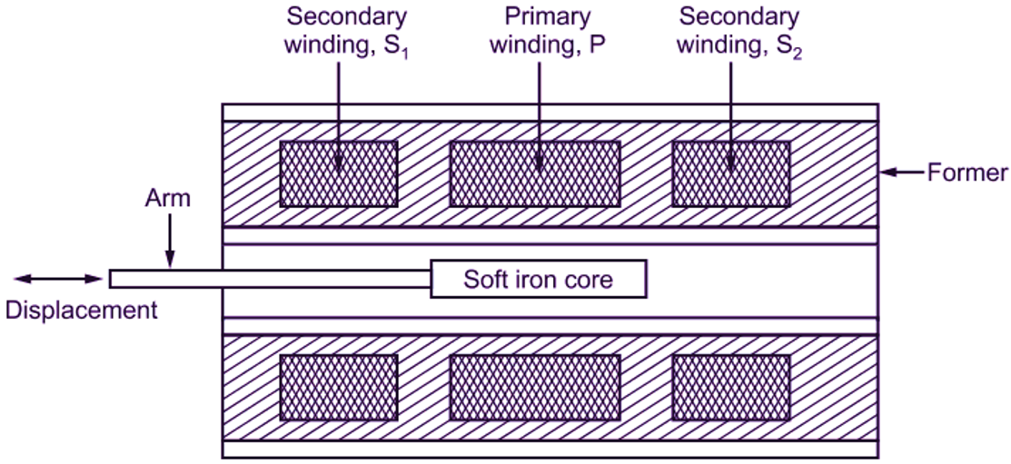
Fig. 1: LVDT
Working of Linear Variable Differential Transformer
When A.C. supply is given to the primary winding, it produces magnetic flux, which completes its path through Sl and S2. While completing the path, the flux produced by the primary winding is linked to the number of conductors of secondary windings. Therefore, according to Faraday’s law of electromagnetic induction, an e.m.f. is produced in the secondary winding. As shown in Fig. 2 (a), the output voltage of S1 is Es1 and that of S2 is Es2. To convert the output of S1 and S2 into single voltage signal, S1 and S2 are connected in series as shown in Fig. 2 (b), with phase difference of 180° (wounded in opposite to each other). Thus, the output of transducer will be the difference of two voltages i.e. differential output voltage. Therefore, Eo = Es1 -Es2
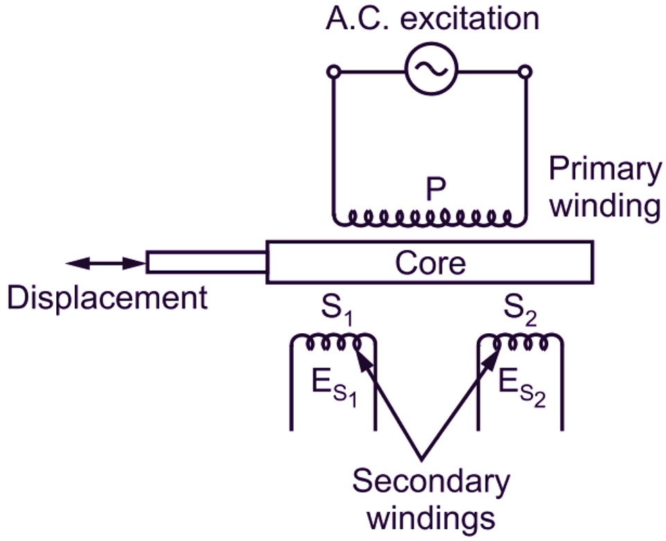
(a)
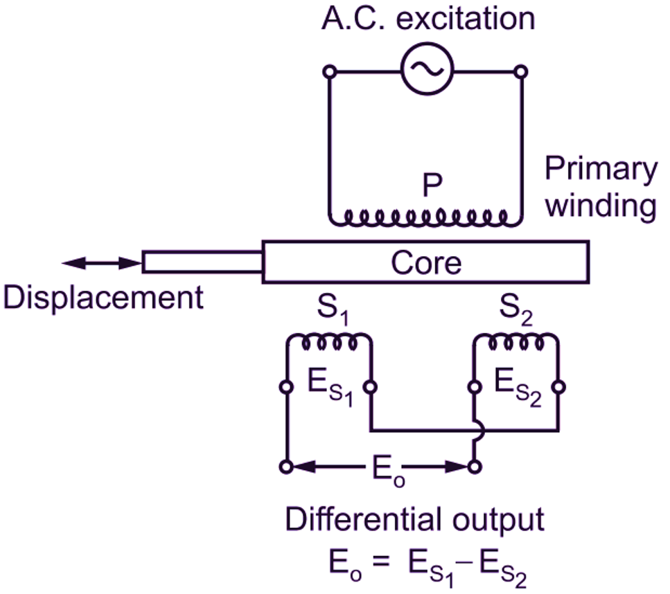
(b)
Fig. 2: Electrical Circuit of LVDT
Various positions of Core and Corresponding Displacement Measurements:
When the core is at central position of insulating cylinder, the magnetic flux linking to both S1 and S2 is equal and hence, equal e.m.f.s. are induced in S1 and S2. Thus,
Es1 = Es2
Therefore,
Eo = Es1 – Es2 = 0
This position of core is called as normal (null) or zero position. It concludes that output voltage is zero at nul position.
When core is moved towards left, then flux inking to coil S1 increases and at the same time, flux linking to coil S2 decreases. Hence, e.m.f. induced in coil S1 (Es1) is greater than of S2 (Es2). As a result of which, output measurement between secondary terminals is in phase with primary voltage.
When core is moved towards the right side, then flux linking to coil S2 (Es2) is more as compared to coil S1 (Es1). Thus, e.m.f. induced in S2 (Es2) is greater than e.m.f. in S1 (Es1). As a result of which, output measurement between secondary terminals is out of phase with primary voltage.
Hence, output voltage (Es1 – Es2) measured between two secondary terminals of LVDT is direct y proportional to the displacement of soft magnetic core.
Advantages of LVDT
- High range for measurement of displacement.
- Less friction and electrical isolation.
- Immunity (protection or exemption from obligation/ penalty) for external effects.
- High input and high sensitivity.
- Rigid in construction.
- Low hysteresis. i.e. very small amount of current remains in electrical circuit.
- Low power consumption.
- Linearity i.e. Linear output over a wide range of motion.
- High output voltage.
- Infinite resolution.
Disadvantages of LVDT
- Large displacement requirement.
- The frequency of carrier must be at least ten times the highest frequency of component to be measured.
- Temperature affects the performance of transducer.
- Vibrations affect the performance of transducer.
- Residual voltage problem.
- Limited dynamic response.
Applications of LVDT
- LVDT can be used for displacement measurement ranging from fraction of 1 mm to a few cm.
- Acting as a secondary transducer, LVDT is used to measure force, weight and pressure.
- Useful for measurement of tension in rod, cord, cable, wire rope etc.
- Useful for measurement and control of thickness of metal sheet.
- Useful for measurement of displacement in CNC machines.
CHARACTERISTICS OF LVDT
- The output voltage’s proportional to the displacement of iron core.
- Negligible operating force and no wear of moving parts.
- The device is very sensitive and it is capable to sense direction of movement of displacement sensor and accordingly, it gives (± x) output.
- Simplicity of design, ease of fabrication and installation, rugged and durable construction.
- It is insensitive to the temperature change of the measurement system.
- High output, low hysteresis, continuous (infinite) resolution and linear electrical response.
- Small physical size and better repeatability.
- Ideally, the output voltage at nul position should be zero, but in actual practice, there exists a small voltage at null position. This is because of presence of some harmonic in the input supply voltage due to the use of iron core. Due to this, Incomplete magnetic or electrical unbalance results into a finite output voltage at null position. This finite output voltage at zero displacement is also called as residual voltage. This is less than 1
- When the core is moved in one direction from the null position, the differential output voltage will increase. This differential voltage i.e. output voltage of LVDT is a linear function of core displacement within a limited range of movement; say about 5 mm from null position. The figure shows variation in output voltage against displacement. For different positions of core, the curve is practically linear for small displacement (say about 5 mm). Beyond this range of displacement, the curve starts to deviate from straight line.
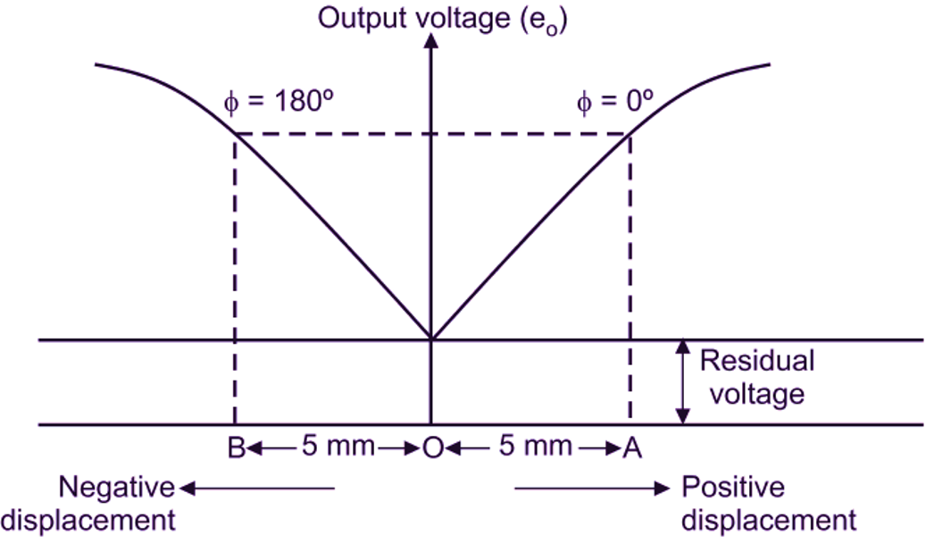
Fig. 3: Displacement versus Output Voltage
SPECIFICATIONS OF LVDT
- Range = 0 to 50 mm.
- Accuracy = 0.1
- Ambient temperature = – 40° to + 50° C.
- Input frequency 20 to 50 kHz.
- Resolution 2 x 10⁻³ mm
- Input or excitation voltage = 3 to 15 V (sinusoidal)
- Stroke or core displacement 0.1 mm to 100 mm.