Venturimeter is a device used to measure rate of discharge in a pipeline. It is fixed permanently at different sections of pipeline to know the discharges at those sections.
Construction of Venturimeter

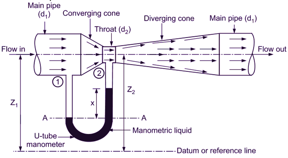
Fig. 1: Venturimeter.
Venturimeter consists of following three parts:
Convergent cone
It is a short pipe, which converges from a diameter d1 (diameter of pipe, in which, Venturimeter is fitted) to a smaller diameter d2 (diameter of throat). The throat ratio varies between d2 / d1 varies between 1 / 4 or 1 / 5. In other words, the slope of converging cone is between 1 in 4 or 1 in 5.
Throat
It is a short pipe having diameter d2, connected between converging and diverging cones. Diameter of throat varies between 33
Divergent cone
It is a long pipe, which diverges from a diameter d2 to original pipe diameter d1.
Working of Venturimeter
One end of U-tube differential manometer is connected to the pipe at entrance section (before converging section) and another end is connected at the throat. This differential manometer is used for the measurement of pressure difference. When the liquid flows through the venturimeter (converging cone), its flow is accelerated resulting in an increase in velocity. Therefore, the velocity of liquid at section 2 (throat) becomes higher than that at section 1. This decreases the pressure at section 2. When the liquid flows through divergent cone, its flow is decelerated (Retarded). As a result of this retardation, the velocity of decreases with subsequent increase in pressure. Thus, venturimeter works on the principle of converting pressure energy (head) into kinetic energy by reducing cross-sectional area of flow passage. This leads to pressure difference, which is measured by means of U-tube differential manometer.
Flow rate of fluid can be measured using the equation/ formula given below:
\[{{\text{Q}}_{\text{act}}}=\frac{{{\text{C}}_{\text{d}}}{{\text{A}}_{1}}{{\text{A}}_{2}}}{\sqrt{\text{A}_{1}^{2}-\text{A}_{2}^{2}}}\cdot \sqrt{2\text{gh}} \]
Where,
Cd = Coefficient of discharge = 0.64
h = Pressure difference in m
A1 = Area of pipe in m2
A2 = Area of Vena-contracta in m2
Advantages of Venture Tube
- It causes low permanent pressure loss.
- It is widely used for high flow rates.
- It is available in very large pipe sizes.
- It is more accurate over wide flow range than orifice plates.
Disadvantages of Venture Tube
- High cost.
- It is not useful for pipe diameters less than 76.2 mm.
- Difficult to inspect due to complex construction.
Applications of Venture Tube
For flow measurement of,
- Water.
- Fluid used in industrial processes.
- Industrial wastes.
- Slurries and dirty liquids.
- Fluids with suspended particles.