Hall Effect Transducer works on the principle that whenever a thin plate of conducting material carries current in presence of transverse magnetic field, an e.m.f is produced between the opposite edges of the thin plate conductor which is given by,
\[{{\text{V}}_{\text{H}}}\text{ }=\text{ }{{\text{K}}_{\text{H}}}\frac{\text{IB}}{\text{t}}\]
Where,
KH = Hall-effect coefficient
I = Current passing through conductor, Amp
B = Magnetic flux density, Wb/m2
t = Thickness of conductor, in.
Therefore, the voltage is proportional to the current and field strength. Metals and Semiconductors cati be used as the conducting plate.
Working of Hall Effect Transducer
The arrangement of Hall effect transducer is shown in
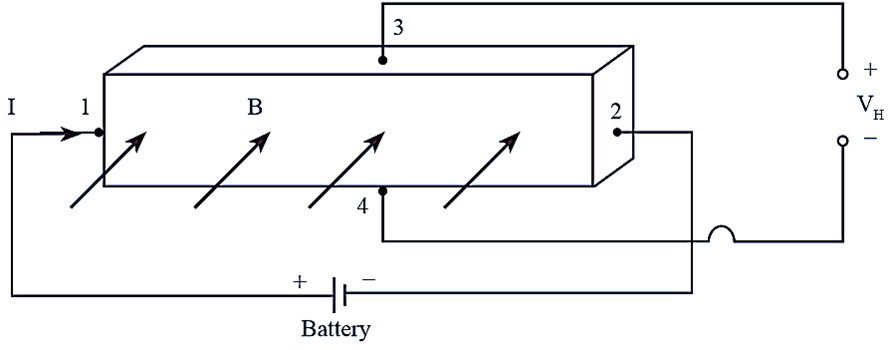
Figure (1): HaIl Effect Transducer.
The thin plate of conducting material is connected to a battery so that current I flows through leads 1 and 2 of the conducting plate. The direction of flow of electrons is opposite to the direction of current I. The output terminals that are connected to leads 3 and 4 are at the same potential when no transverse magnetic field passes through the conducting plate.
Now, when the magnetic field is applied in a direction perpendicular to the conducting plate then the electrons are pulled towards the top of conducting plate because of magnetic field. Therefore, excess of electrons are present at the top of plate and lack of electrons at the bottom of the plate. This results in creation of potential difference (VH) between the top and bottom of the plate. The phenomenon of hall effect is more pronounced in semiconductors as compared to metals.
Applications of Hall Effect Transducers
The various applications of hall effect transducers are discussed below
Measurement of Displacement
Hall effect element may be utilized for measurement of linear displacement of structural element with respect to ferromagnetic plate. Such an arrangement is shown in figure (2).
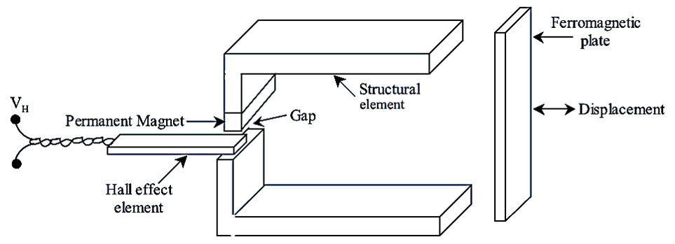
Figure (2): Measurement of Displacement
In this, change in dimensions of a magnetic structure causes a change in magnetic flux density. Figure (2) shows a structural element having a pennanent magnet. The Hall effect element is placed inside the gap close to permanent magnet. Now as the position of a ferromagnetic plate is changed, the field strength of the gap in which Hall effect element is present changes. The output voltage (VH) produced at the Hall effect transducer is proportional to magnetic field strength in the gap or proportional to displacement of ferromagnetic plate with the structure. Therefore, displacement can be measured by using a Hall effect transducer. This method allows measurement of very small displacements of about 0.025 mm.
Measurement of Current
The Hall effect transducer measures current carried by conductor without causing interruption in the circuit and without the need of placing ammeter. When current passes through the conductor then a magnetic field is set up surrounding the conductor. The hail effect transducer is placed in the slot of magnetic concentrator which collects the magnetic field as shown in figure (3).
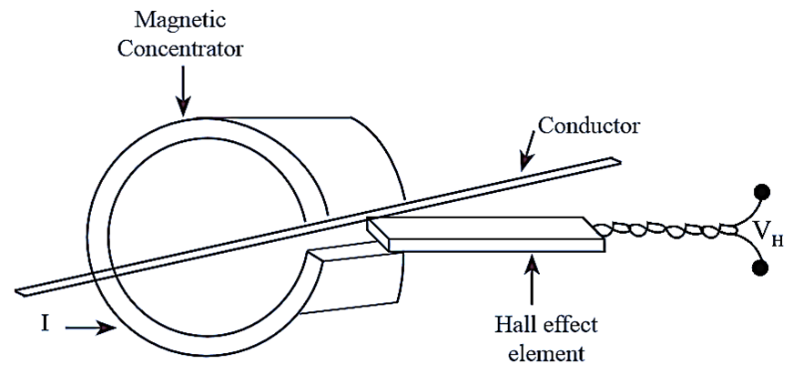
Figure 3: Measurement of Current
The output voltage of Hall effect transducer is proportional to magnetic field strength which depends on the current flowing through the conductor. When the current level is high, the magnetic concentrator is eliminated from the circuit. This method allows measurement of currents less than 1 milliampere to thousands of amperes. Since the magnetic field around the hail effect element is strong, the output voltages are produced which are easy to identify.
Measurement of Magnetic Field
The hall effect transducer can be employed as magnetic to electric transducer. It consists of a semiconductor plate carrying current that is placed orthogonally with the magnetic field to be measured. This produces a voltage difference across the plate that is directly proportional to the magnetic field strength. The advantage of this system is that it requires very less space in the direction of the magnetic field. Therefore, the hall element can be placed in small gap to measure magnetic field in air space. Also, continuous electric signal is given by hall element due to the magnetic field.