Data loggers are the devices used to measure and store the readings of instruments without any loss of accuracy. They are the application of data acquisition system. The output of a transducer can be measured and the value is logged automatically by the data loggers. They also take care of suitable corrective action if the output signal goes beyond the predefined range.
Block Diagram of Data Logger
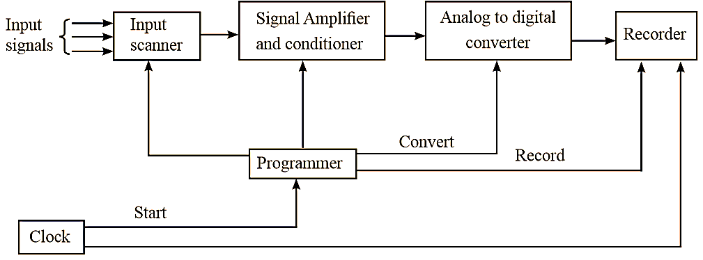
Figure 1: Data logger.
The block diagram of basic data logger is as shown in figure 1. The basic parts of a data logger are explained as follows.
1. Input Scanner
The various input signals fed to the input scanner are temperature, pressure, vibrations, ON/OFF signals etc. The input scanner is an automatic switch that can select only one input signal at a time. In modem scanners the rate of scanning is upto 150 inputs.
2. Signal Amplifier and Conditioner
The input signal selected by scanner is a low level signal. Hence a signal amplifier is used to amplify the low level signal so that the input signal is maintained at 5 V level. The signal amplifier should possess certain characteristics like precise and stable D.C gain, high signal to noise ratio, good linearity, high impedance etc.
The signal conditioner is placed between scanner and analog to digital converter. It is a linearising circuit i.e., if a signal varies non linearly with respect to the measured parameter then linearization of signal is done by the signal conditioner.
3. Analog to Digital Converter
The data loggers handle the data only in digital form and hence the analog signal, if any, have to be converted into digital form by employing analog to digital converter. The digital technique is used because it measures very small signals without loss of accuracy. The analog signals that are converted to digital form are suitable to drive the digital recorders.
4. Recorder
The data logger drives the output recorder which prints the signals obtained from the analog to digital converters. The recorder may consist of either typewriter or a punched tape. The typewriter provides a conventional log sheet with results in tabular form. Punched paper tape is used when the recorded data has to be analysed further in a digital computer.
5. Programmer
It controls the sequence of operation of all other units of data logger. It takes information from input scanner, analog to digital converter and recorder. The programmer performs various functions like starting analog to digital conversion, selecting input signal by scanner, recording and displaying reading, resetting logger etc.
6. Clock
The logging sequence is started automatically by a clock. The clock is used to automate the entire data logging system. When the clock signal is generated the scanning operation is started then the data logger advances ahead by time. The clock gives command to the programmer to start logging sequences at the intervals selected by the user.
Functions of Data Logger
The functions of data loggers are as follows.
- They automatically record the readings of instruments placed at different locations of the plant.
- During the time of emergency, they help in analysing the conditions of alarm logically and also the performance of the plant.
- They initiate corrective action when the readings are beyond the prescribed limits and also note the readings displayed on output devices which are then transmitted to computer for further processing
- They can automatically evaluate and record the output from any transducer