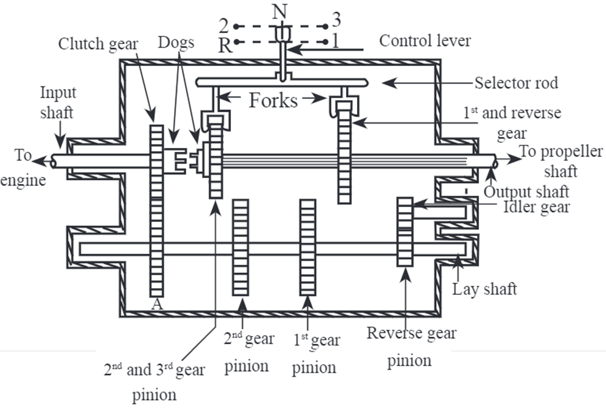
Figure 1: Sliding Mesh Gearbox
Construction & Working of Sliding Mesh Gearbox
The sliding mesh gearbox consists of three shafts namely input shaft, output shaft and lay shaft. The input and output shafts are in line, whereas lay shaft is parallel to them and lies below them. The function of input shaft is to take power from engine and transmit to output shaft through a series of gears mounted on layshaft. The function of output shaft is to transmit power obtained from input shaft to the propeller shaft for onward transmission to road wheels. Schematic layout of sliding mesh gear box is shown in Figure 1.
Input shaft has a clutch gear mounted on it. Clutch gear is in constant mesh with gear A on the layshaft. Gear A is larger than clutch gear. Layshaft has second gear, first gear and reverse gear pinions mounted on it. Pinions and gear A are integrally constructed with layshaft so they cannot be slided on the shaft. Output shaft has two gears mounted on it and has splinted on it. These two gears can slide on output shaft. These gears have forks attached to them on the output shaft and can be moved by a desired selector. Each fork has one selector. Selectors are moved by a control lever at the desire of driver. The control lever motion gives direction as 1, 2, 3 or R depending upon the gear to be engaged like first, second, third or reverse. Its position in neutral gear is marked as N. The direct drive dogs are on the input and the output shafts. These are coupled to each other for engaging top gear In this sliding mesh gear box third gear is the top gear Idler (a pinion) is always in mesh with pinion on a layshaft and is used for engaging the reverse gear. It causes the reversal of rotation.
For changing the gear, clutch should be depressed and lever should be moved till the selector pinion on the main shaft (output shaft) engages with its mating gear on layshaft. When clutch is released, the drive from the engine will be transmitted through the gear box.