In this topic, you study Voltage Regulation of Alternator.
The voltage regulation of an alternator is usually expressed as a fraction or percentage of its terminal voltage on load because the alternator usually works at constant Terminal voltage. To achieve this, the excitation is constantly adjusted to suit different load conditions using automatic voltage regulators. If under the conditions represented by Fig. 1, the load is disconnected, the speed and the field excitation remaining the same, the terminal voltage per phase will change from V to Eo (the effects of armature resistance, leakage reactance and armature reaction being absent). This change in the terminal voltage (i.e. the numerical difference between Eo and V) is known as voltage regulation of the alternator for the given conditions of load and power factor. Thus, voltage regulation of an alternator may be defined as the change in its terminal voltage when a given load is thrown off, the excitation and speed remaining constant.
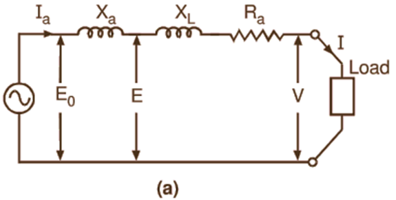
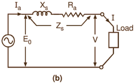
Fig. 1: Equivalent circuit of an alternator.
Formula for Voltage Regulation of Alternator
Voltage Regulation is usually expressed as a fraction or percentage of the terminal voltage on load. Hence in general, if V is the terminal voltage per phase for a given load and Eo is the open-circuit voltage (i.e. no-load terminal voltage) per phase, then
\[\text{Voltage Regulation = }\frac{{{\text{E}}_{\text{o}}}\text{-V}}{\text{V}}\text{ per unit}\]
\[\text{=}\frac{{{\text{E}}_{\text{o}}}\text{-V}}{\text{V}}\text{ }\times \text{ 100 percent}\]
Its value depends not only on the load current but also on the power factor of the load. Fig. 2 shows the load characteristics (relationships between terminal voltage and load current) of an alternator under different power factor conditions. For unity and lagging power factor conditions, there is always a voltage drop with the increase in load current. As such, the voltage regulation is always positive. However, if the load is capacitive with low leading power factor, the terminal voltage may rise with the increase of load current and the regulation will then be negative. Since the voltage regulation of an alternator depends on the load power factor, it is always specified with the load power factor.
Fig. 2: Load characteristics of an alternator under different power factor conditions
Alternators are designed to operate at a desired regulation limit while supplying full load usually at 0.8 lagging power factor. The amount of regulation of commercial alternators may vary from 15
DETERMINATION OF VOLTAGE REGULATION
Many methods have been devised for determining the voltage regulation of an alternator. In the case of a small machine, regulation may be determined by actually loading it. But this method of direct loading is out of the question for large machines because of the prohibitive cost of providing motive power and auxiliary apparatus for absorbing the power output. In fact, in the case of very large machines, it may be impossible to obtain sufficient power required for testing purposes and to find an artificial load of sufficient magnitude. With polyphase alternators, there is the added difficulty of obtaining a balanced load? The large machines are, therefore, generally tested indirectly by simulating the load conditions. A number of such indirect methods have been developed. All these methods are based on simple no-load test and require comparatively little power. Two commonly used indirect methods for determining the regulation of an alternator, namely the synchronous impedance method and m.m.f. method. Thus, the different methods to obtain the voltage regulation of an alternator are:
- Direct-loading method
- Synchronous impedance method or emf method
- Ampere turns method or mmf method
- Zero power-factor method or potier triangle method
Voltage Regulation by Direct Loading method
In the case of a small machine, regulation at any desired load condition and power factor can be found by directly loading the machine as follows:
Circuit Diagram
Fig. 3 shows the schematic circuit diagram for conducting the load test on an alternator for finding its regulation. The loading arrangement may consist of lamp banks, choking coils or a synchronous motor in turn having an arrangement for mechanical or electrical loading (by adjusting the excitation of this synchronous motor, its power factor can be controlled).
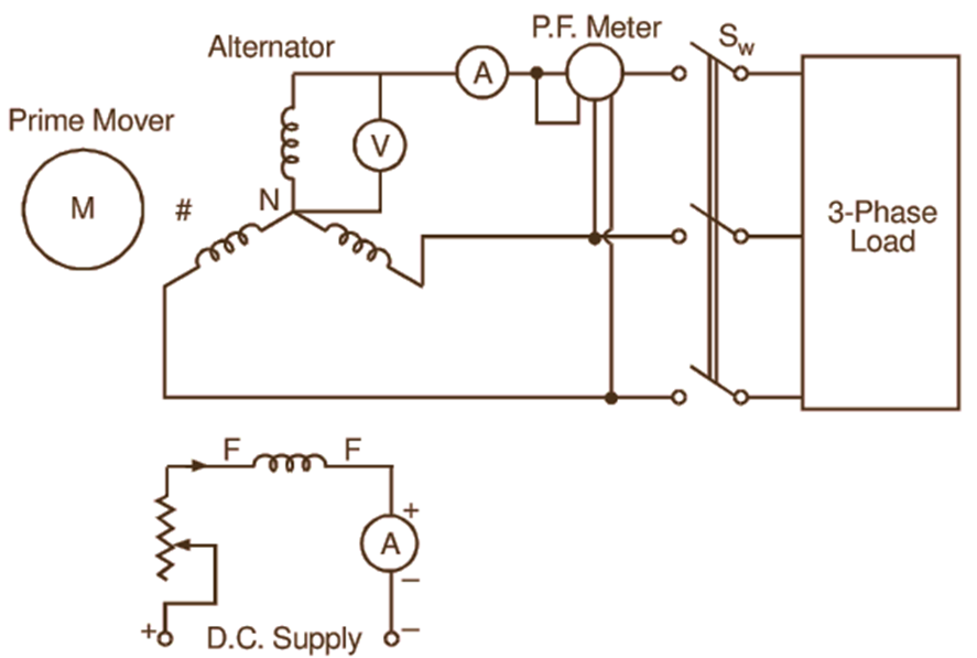
Fig. 3: Schematic diagram for load test on an alternator
Test Procedure
The alternator is driven at synchronous speed using a suitable prime mover. By adjusting the excitation, its terminal voltage (phase value, as in this case, a voltmeter is connected between a phase and neutral) is raised to the rated (or slightly higher) value. Next, the alternator is loaded upto full load at desired power factor with the excitation adjusted to give the rated voltage per phase (V) under this condition. Finally, keeping the speed and excitation constant, the entire load is then thrown off by disconnecting the switch Sw and the open-circuit voltage or no-load terminal voltage (phase value) Eo is observed. All these observations are recorded in a tabular form shown below.
Table for Observations
| Sr. No. | V | I | Power Factor | Eo |
Regulation Calculations
From the above observations, regulation of the alternator at any desired power factor can be calculated as follows:
What types of regulators are used for voltage regulation in alternators?
The voltage regulation can be obtained by these two ways:
- Manual
- Automatic.
Manual control: It is not a convenient method of controlling the voltage, because for manual operation it is difficult. In this method we control the field current flowing through the field winding of the alternator, it is difficult to control manually because the load on the alternator is not known at a particular time it depends upon the consumers and their needs.
Automatic control: Whenever a sudden change of alternator load occurs, demanding a change in the field excitation to arrange the constant voltage under the new load conditions, the regulator must operate for the exciter field to give sufficient current to develop same voltage under all load conditions. When this arrangement is done automatically the system is called automatic control.
These regulators are of two types:
- Vibrating contact type.
- Sliding contact type.
Solved problems on Voltage Regulation by Direct Loading method
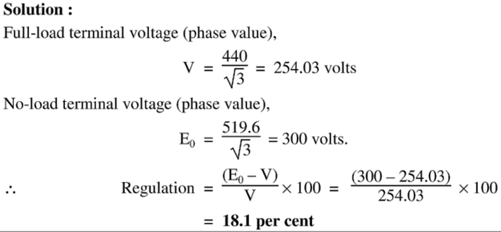
Example 1
When a three-phase, star-connected alternator is fully loaded at 0.8 lagging power factor, the terminal voltage (line value) is 440 V. On throwing of this load, with speed and field excitation being maintained constant, the voltage rises to 519.6 V. Calculate its voltage regulation.