In this topic, you study Voltage Regulation of Transformer.
We are familiar with the fact that in the case of a cell, the terminal voltage is always less than its e.m.f. when it delivers current to the load due to the voltage drop caused by its internal resistance. Similar is the case of a transformer. When the transformer is not delivering any current to the load, voltage available across its secondary terminals V02 is equal to the induced e.m.f. (E2) in the secondary winding. But as soon as the transformer starts delivering current to the load, due to internal voltage drop caused by the combined effect of impedances of both the windings, the secondary terminal voltage falls to V02 (assuming the normal inductive or resistive load conditions) from its no-load value. With the increase in the current delivered, the resistance and leakage reactance drops of the primary winding cause a decrease in the value of primary induced e.m.f. (E2). This produces a proportional decrease in the flux and hence in the secondary induced e.m.f. The secondary terminal voltage is then further reduced by the resistance and reactance drops of the secondary winding. The effect of load on the secondary terminal voltage can be more easily understood from the simple equivalent circuit of a transformer referred to the secondary side shown in Fig. 1.
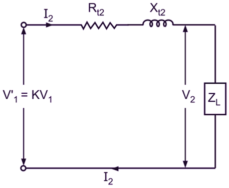
Fig. 1: Equivalent circuit of Transformer
With I2 = 0, there will be no internal voltage drop in the impedance of the windings. Hence, the voltage available at the secondary terminals (V02) under this condition will be
\[\text{V}_{1}^{‘}=\text{K}{{\text{V}}_{\text{1}}}=\text{K}{{\text{E}}_{\text{1}}}={{\text{E}}_{\text{2}}}\]
But on load, due to voltage drop in the impedance of the windings, the secondary voltage will change from its no-load value and will be given by
${{\text{V}}_{2}}=\text{K}{{\text{V}}_{\text{1}}}-{{\text{I}}_{\text{2}}}\left( {{\text{R}}_{\text{t2}}}+\text{j}{{\text{X}}_{\text{t2}}} \right)$ (Phasor difference)
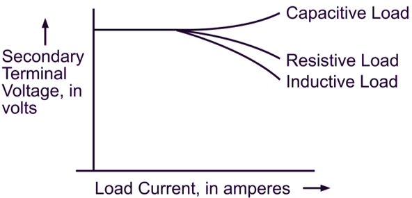
Fig. 1: Effect of the nature of the load on regulation
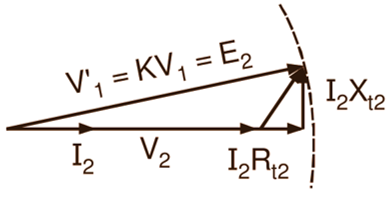
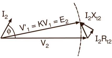
The secondary terminal voltage depends not only on the magnitude of the load current but also on the power factor of the load (Fig. 1). With inductive loads such as motors and resistive loads, the secondary terminal voltage decreases with the increase in the load on the transformer, while with capacitive loads having low leading power factors, it may even increase. The effect of power factor on the secondary terminal voltage can be very well seen from the phasor diagrams (again based on the simple equivalent circuit referred to the secondary side) of Fig. 2 drawn for a constant primary impressed voltage (V1) and load current (I2). The change of power factor causes the impedance triangle to swing round. Under unity power factor conditions (Fig. 2 (a)), the fall in the secondary terminal voltage on load is mainly due to the resistance drop (I2Rt2), the reactance drop (I2Xt2) having little effect.
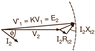
On the other hand, under lagging power factor conditions (Fig. 2 (b)), the fall in the secondary terminal voltage is mainly due to the reactance drop (usually, the reactance is considerably greater than the resistance). When the power factor is leading, the reactance has just the opposite effect. As a result, fall in the secondary terminal voltage on load decreases. If the power factor is sufficiently low (Fig. 2 (c)), the secondary terminal voltage actually rises on load.
(a)
(b)
(c)
Fig. 2: Phasor diagrams (based on simple equivalent circuit, referred to secondary) for a transformer on load with (a) unity p.f., (b) lagging p.f. and (c) leading p.f.
The numerical difference between the values of the secondary terminal voltage on no load (V02 = E2) and with full load is of importance to the user and is known as the inherent voltage regulation of the transformer. The regulation of the transformer is, therefore, defined as the change in the secondary terminal voltage from no load to full load with primary impressed voltage (V1) and Temperature of the transformer maintained constant. The regulation is usually expressed as percentage of the no-load secondary terminal voltage. Thus,
\[\text{Voltage regulation}=\frac{{{\text{V}}_{02}}-{{\text{V}}_{2}}}{{{\text{V}}_{02}}}\times 100\]
\[=\frac{{{\text{E}}_{\text{2}}}-{{\text{V}}_{2}}}{{{\text{E}}_{\text{2}}}}\times 100\text{ percent}\]
Referring to the simple equivalent circuit of the transformer referred to the primary side shown in Fig. 3, the regulation may also be expressed in terms of the corresponding quantities referred to the primary side.
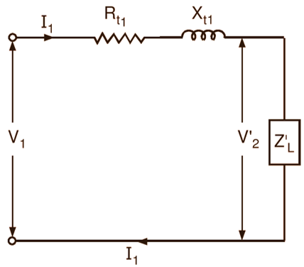
Fig. 3: Equivalent circuit of the transformer
On no load, the secondary terminal voltage of the transformer referred to the primary side will be V1. On load, it will be given by,
$\text{V}_{_{2}}^{‘}={{\text{V}}_{\text{1}}}-{{\text{I}}_{\text{1}}}\left( {{\text{R}}_{\text{t1}}}+\text{j}{{\text{X}}_{\text{t1}}} \right)$ (Phasor difference)
Hence,
\[\text{Voltage regulation}=\frac{{{\text{V}}_{1}}-\text{V}_{2}^{‘}}{{{\text{V}}_{1}}}\times 100\text{ percent}\]
It should be remembered that regulation is always positive for the inductive load with lagging power factor and resistive load with unity power factor and may be negative for the capacitive load with leading power factor. Voltage regulation being dependent on the power factor of the load, it is always specified with the load power factor. The transformer having less regulation and therefore more or less constant secondary terminal voltage is always considered as a good transformer.