In this topic, you study Direct Load Test on Transformer.
Efficiency and regulation of a transformer at any desired load condition and power factor can be found by either directly loading the transformer or by conducting the open circuit and short-circuit tests. The method of finding the efficiency and regulation by direct loading is rarely used for large transformers because of the difficulty of obtaining a suitable load and the large loss of power involved during testing. On the other hand, the open circuit and short-circuit tests can give the desired results without actually loading the transformer. It is for this reason, this method is known as indirect method of testing the performance of the transformer. The power required to carry out the open circuit and short-circuit tests on the transformer is also very small compared with the method of direct-loading and the results obtained are also more accurate. Thus, efficiency and regulation at any desired condition and power factor can be found by directly loading the transformer as follows:
Experimental Set-up of Direct Load Test on Transformer
Fig. 1 shows the necessary connection diagram for the test. The primary of the transformer is connected to an ac supply of rated voltage through the instruments like an ammeter, a voltmeter and a wattmeter. A variable load is connected across the secondary. One ammeter, one voltmeter and one wattmeter are also inserted on the secondary side as shown.
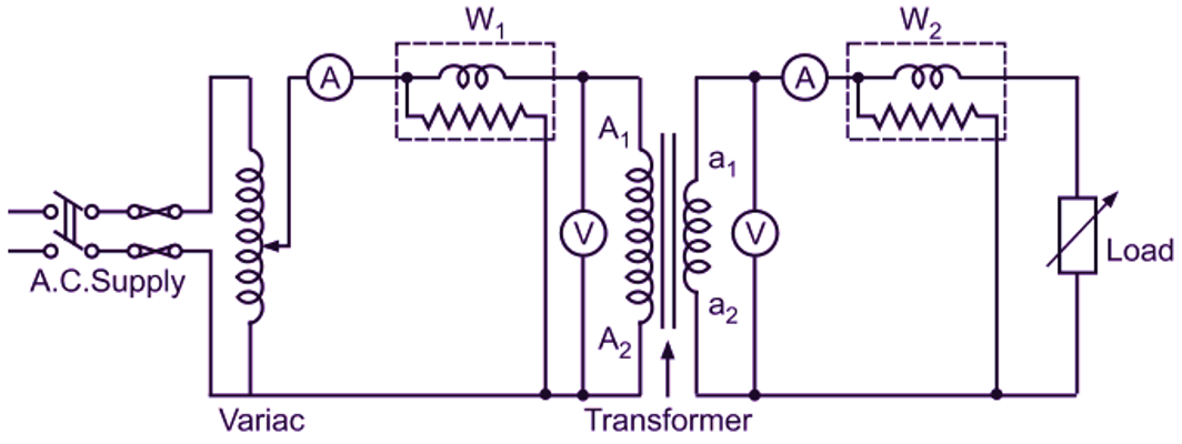
Fig. 1 Direct loading of a single phase transformer
Procedure of Direct Load Test on Transformer
By varying the load in suitable steps, readings are taken on all meters from no load to about 25
Table for Observations of Direct Load Test on Transformer
| Sr. No. | Primary Side | Secondary side | ||||
| V1 | I1 | W1 | V2 | I2 | W2 | |
Calculations for Efficiency
The wattmeters on the primary and secondary sides respectively read the input (W1) and output (W2) powers.
\[\text{Efficiency}=\frac{\text{Output power}}{\text{Input power}}\times 100\]
\[=\frac{{{\text{W}}_{2}}}{{{\text{W}}_{1}}}\times 100\text{ percent}\]
If the load is purely resistive (with unity power factor) like lamp-bank, then the wattmeter on the secondary side can be eliminated. This is because with unity power factor loads, output power is also given by the product V2I2.
\[\text{Efficiency}=\frac{{{\text{V}}_{2}}{{\text{I}}_{2}}}{{{\text{W}}_{1}}}\times 100\text{ percent}\]
Calculations for Regulation
Under no-load condition (i.e. when secondary circuit is open and I2 = 0), the voltmeter reading on secondary side gives no-load secondary terminal voltage. Let us call it V02. Then for each reading, regulation is given by
\[\text{Voltage regulation}=\frac{{{\text{V}}_{02}}\text{ – }{{\text{V}}_{2}}}{{{\text{V}}_{02}}}\]
The voltage regulation will be in percent. And where,
V2 = Secondary terminal voltage on load.
Graphs
From the results obtained, curves alt plotted for the efficiency and regulation against the current or output power as illustrated in Fig. 2.
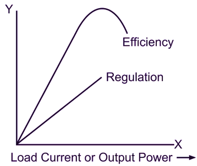
Fig. 2: Efficiency and regulation curves
Then, the efficiency and regulation at any desired load can be found from these curves.