In this topic, you study Isolation Transformer – Definition, Theory & Diagram.
The transformer is frequently used to isolate one portion of an electrical system from another. Eventhough these parts are physically separated, they remain magnetically coupled to each other. The transformers which are specially designed to provide electrical isolation between the primary and secondary circuits, without change in the voltage and current levels are called isolation transformers.
Special Features of Isolation Transformer
The conventional two winding step-up and step-down transformers can provide the electrical isolation between their primary and secondary circuits. The only difference between the conventional two winding transformer and the isolation transformer is that the isolation transformer is a 1:1 transformer (i.e. with N1 = N2) and is used only for the purpose of electrical isolation. Obviously, in general, the construction of an isolation transformer is identical to that of the conventional two winding transformer. However, it is generally provided with inbuilt filtering and protective circuits.
Functions of Isolation Transformers
Following are the two principal functions of the isolation transformers :
- Isolation transformers isolate and protect the sensitive and expensive equipments from electrical system grounds. As an illustration, consider the case of application of the voltage vx to the vertical input of the oscilloscope (a measuring instrument). If the connections are made as shown in Fig. 1 (a), with the generator and oscilloscope having a common ground, the impedance Z2 is effectively short circuited. The input voltage to the oscilloscope will therefore be meaningless as far as the voltage vx is concerned. In addition, with the shorting of Z2, the current in the circuit may rise to a level that will cause severe damage to the circuit. If the isolation transformer is used as shown in Fig. 1 (b), this problem will be eliminated, and the input voltage to the oscilloscope will be vx.
- Isolation transformers protect the delicate and expensive equipments against voltage spikes.
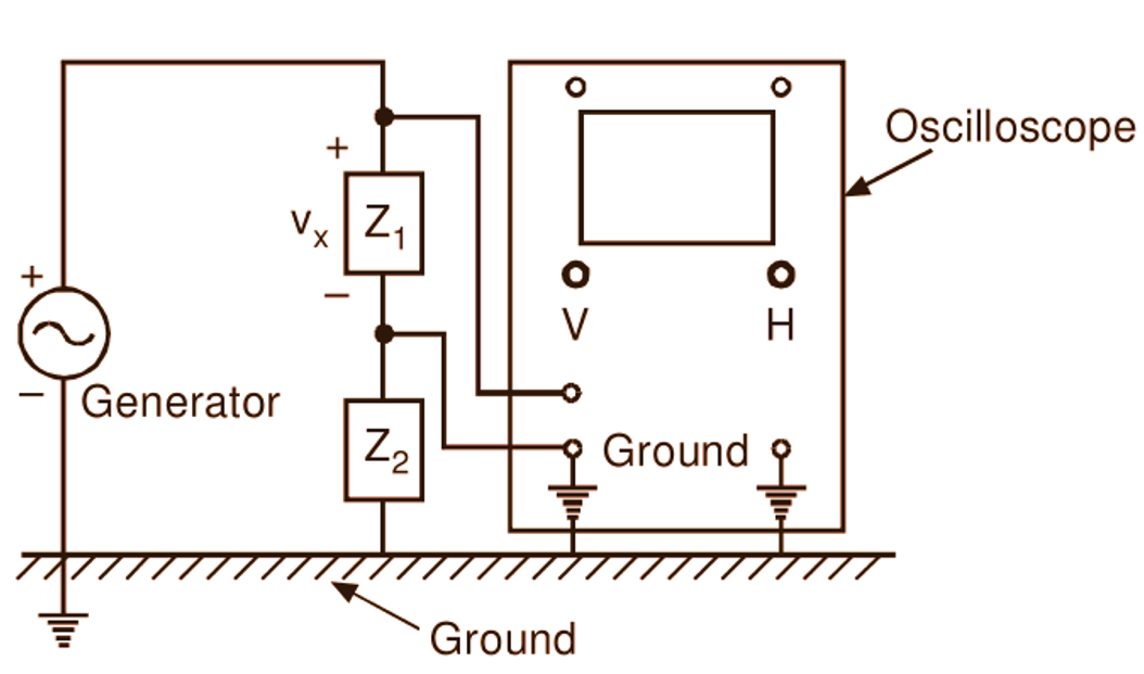
(a)
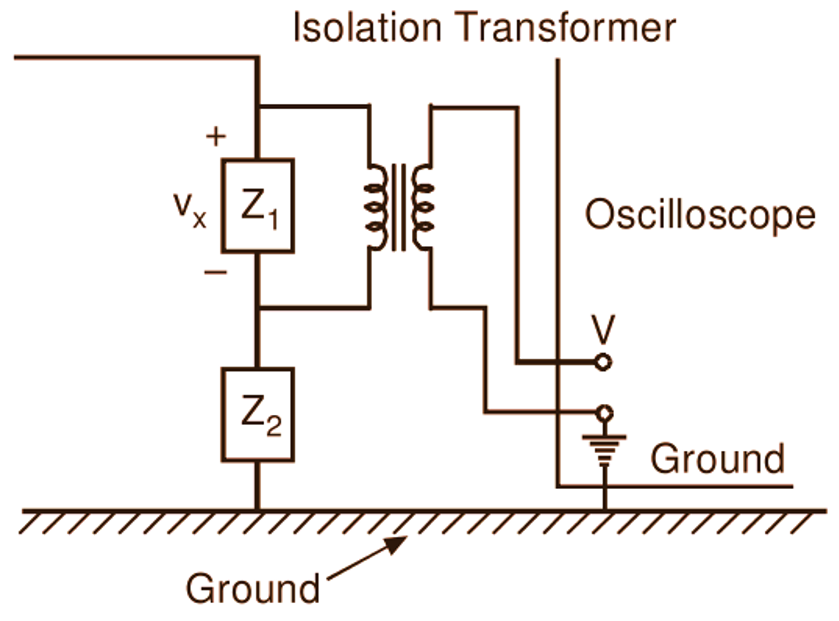
(b)
Fig. 1: Use of an isolation transformer with the oscilloscope
Voltage spikes are short-duration high-amplitude pulses which get superimposed on the normal a.c. supply voltage. Such voltage spikes can cause a damage to the equipments, create audio and video signal distortions and may result into the loss of data (in the case of equipments like computers). Isolation transformer with its inductive windings, reduces the amplitude of the voltage spike before it reaches the equipment as illustrated in Fig. 2.
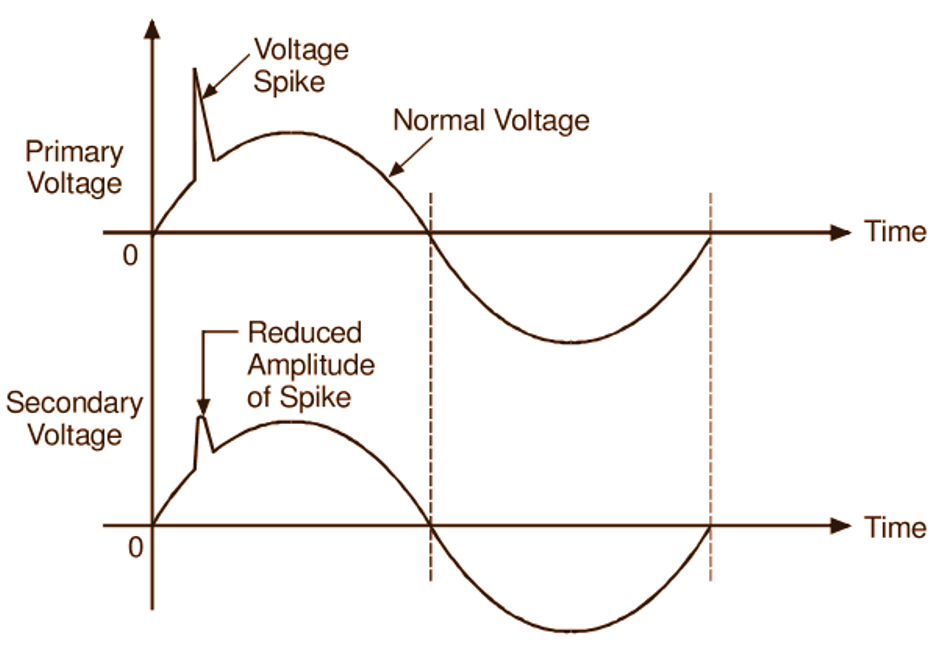
Fig. 2: Reduction of amplitude of voltage spike using an isolation transformer