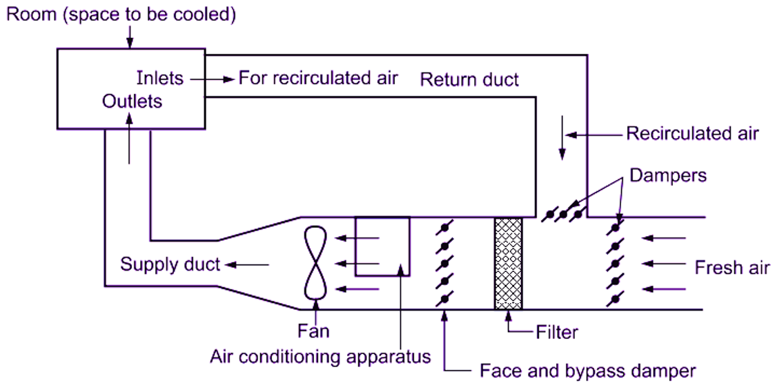
The Air Handling Unit (AHU) unit consists of:
Air distribution system: It includes various inlets for re-circulated air and ducts for the supply air.
Duct system: It includes the return duct, supply duct and air conditioning apparatus including dampers, filters, coils or air washer.
Fan: It provides necessary energy (mechanical work) to move the air.
Fig. 1 shows schematic air flow diagram for an air conditioning system. It shows the closed loop formed due to method used for circulation of air. In this loop, the point is room itself, which can be considered at atmospheric pressure. Through the inlets, the recirculated air enters into the return duct and it continues to drop in pressure until it reaches the fan. The fan raises the pressure of air. This pressure starts dropping again, until the air enters the space to be cooled. Therefore, the pressure is positive on the discharge side of the fan and negative on the suction side.

Fig. 1: Air flow diagram
Principles of Air Handling Unit (AHU)
- Air should be distributed in the room, so that, the required temperature, humidity and air velocity are maintained in the occupied zone of about 1.8 m above the floor.
- Air stratification, temperature difference, dead pockets, high drafts, stagnation layers and convection currents must be avoided.
- There should be thorough (enough) mixing of the ‘conditioned air’ (discharged into the room through outlets) with the ‘air inside the room’
- The temperature difference in the room should not be larger than 1°C.
- The velocity should be in the range of 7 m/min to 17 m/min to avoid low or high drafts. Down flow and flow directed to the faces of people is preferred than the upward flow and flow directed to backs or sides of people.
- The exhaust and inlet points must be so arranged that, fresh air is available in all parts of the room.