Ducts are defined as, “paths for supply air and return air”. Ducts are generally made up of galvanised iron sheet metal or aluminium sheet metal of thickness 16 to 26 gauge.
Functions of a duct
- To ‘convey the conditioned air between two points’. For example: From the air handling unit (AHU) to the room to be conditioned.
- To convey the room air (recirculated air) back to the air conditioning apparatus.
Now-a-days, some non-metallic materials are preferably used for manufacturing of ducts.
For example
- Resin bonded glass fiber ducts because they are strong and easy to manufacture.
- Cement asbestos ducts are used for underground air distribution and for exhausting corrosive materials.
- Wooden ducts may be used in places, where moisture content in air is not very large.
Ducts may be circular, rectangular or square in cross-sect-on. Refer Fig. 1.
Rectangular duct: Most commonly used cross-section is the rectangular duct, because it provides flat surface and It is easier to work with room surface.
Square duct: From practical point of view, square duct is preferred due to their aesthetic appearance and symmetry in cross-section.
Circular duct: Circular duct is economical, because it can carry higher amount of air in less space as compared to other ducts. If required duct material is ess, it means that, there will be less surface and hence, less friction.
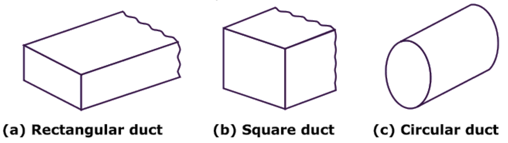
Fig. 1: Various cross-sections of duct
Classification of Duct
The ducts may be classified,
According to type of air in duct
Supply air duct: The duct, which supplies the conditioned air from the air conditioning equipment to the space to be air conditioned, is called as supply air duct.
Return air duct: The duct, which carries the re-circulating air from the air conditioned space back to the air conditioning equipment, is called as return air duct.
Fresh air duct: The duct, which carries or brings the outside air towards air conditioning equipment, is called as fresh air duct.
According to pressure of air in duct
Low pressure duct: When the static pressure in the duct is less than 50 mm of water gauge, the duct is said to be low pressure duct.
(b) Medium pressure duct: When the static pressure in the duct is up to 150 mm of water gauge, the duct is said to be medium pressure duct.
(c) High pressure duct: When the static pressure in the duct is more than 150 mm of water gauge, the duct is said to be high pressure duct.
According to velocity of air in duct
(a) Low velocity duct: When the velocity Of air is up to 600 m/min., the duct is said to be low velocity duct,
(b) High velocity duct: When the velocity of air in duct is more than 600 m/min., the duct is the said to be high velocity duct.
According to cross-section
- Rectangular duct
- Square duct
- Circular duct
DIFFERENT LAYOUTS OF DUCTS FOR CENTRAL AIR CONDITIONING UNIT
Air distribution system (ducting) mainly consists of supply ducts and return ducts. The most commonly used duct systems are,
- Closed perimeter OR Loop perimeter system,
- Extended plenum system
- Radial perimeter system, and
Closed Perimeter Or Loop Perimeter System
Central air conditioning unit is placed in the basement of building and the conditioned air from central air conditioning plant is brought to central plenum. From central plenum, conditioned air is carried to several feeder ducts to a common continuous closed loop around the outer perimeter of the building. The outlets provided at the outer perimeter of building are used to supply conditioned air to the room.
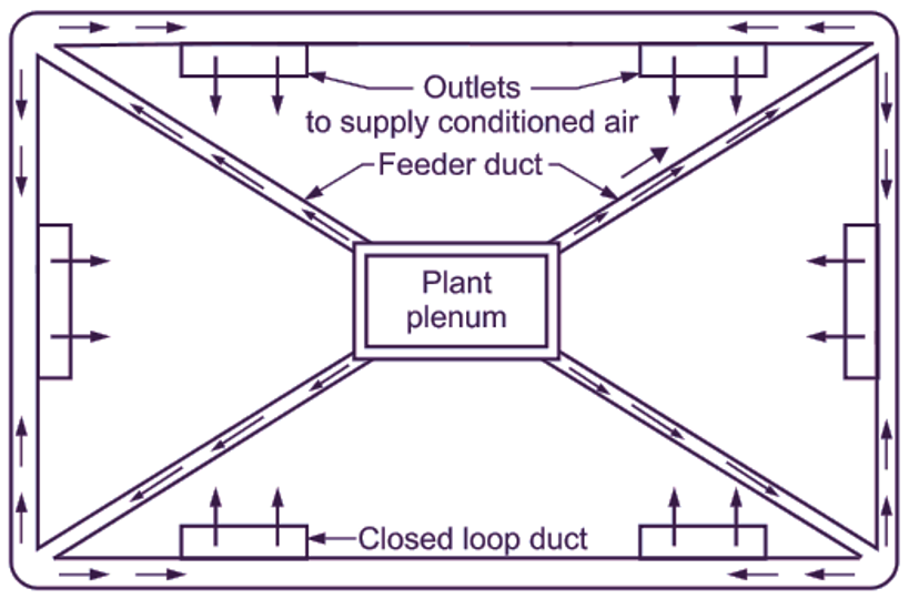
Fig. 2: Closed perimeter or Loop perimeter system
Radial Duct System
Air from central air conditioning plant is brought to plant (central) plenum, from which, it is carried from separate duct to each outlet. This type of arrangement is commonly used in residential buildings.
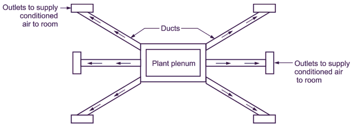
Fig. 3: Radial duct system
Extended Plenum System
This system is mostly used in small residences and commercial buildings. Here, the conditioned air can be supplied directly from the main duct (large) and its various branch ducts (small). The central air conditioning plant can be placed away from the rooms. Conditioned air is supplied from the main duct (extended plenum) to number of branch ducts (small). The outlets provided at these branch ducts are used to supply the conditioned air to all the rooms. This system can be divided into single duct system and dual duct system on the basis of number of main ducts used.
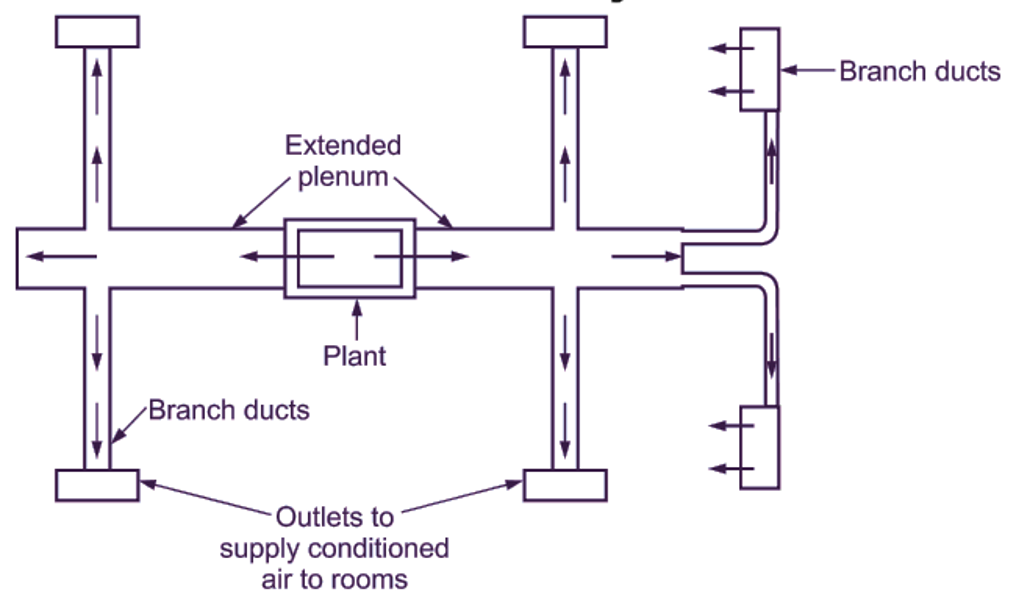
Fig. 4: Extended plenum duct System
Duct Materials
The ducts are usually made from,
Metals
Galvanized iron sheet metal: Galvanized iron (G.I.) sheet metal is the most commonly used duct material. Zinc coating of this metal prevents rusting and avoids the painting cost. Thickness of galvanized iron (G.I) sheet used for ducting is in the range of 0.5 mm to 1.5 mm.
Aluminium sheet metal: It is used because of its lighter weight and better resistance to moisture.
Stainless steel: It is used in special applications to offer greater or max-mum resistance against moisture/humidity.
Non-metals
Resin bonded glass fibre: It is used due to its strength and easy to manufacture property according to the desired shape and size. Its use is preferred in low velocity applications.
Wooden ducts: They are suitable for places, where moisture content in air is less.
Cement asbestos: They are preferred for underground air distribution systems and for exhausting corrosive materials.
DESIRABLE PROPERTIES OR REQUIREMENTS OF DUCT MATERIALS
- Enough strong to sustain (withstand) against load, vibrations and excessive pressure.
- Light weight.
- Easy to fabricate.
- Non-flammable and fire proof.
- More durability.
- Low cost.
- Odourless.
- Non-corrosive and Non-reactive.
- Low tendency to absorb moisture.
- Low thermal conductivity.
Losses in Duct System
The various losses in duct system are,
Surface friction loss
Frictiona losses depend upon,
- air velocity,
- design of duct,
- roughness of interior surface of duct,
- length of duct.
Loss due to change in direction
Some losses take place due to change in direction of air. Loss of head is maximum, when air is forced to change its direction by 90°. Therefore, use of sharp right-angled bend (90° bend) is avoided.
Loss due to sudden enlargement
When flow (sectional) area increases, velocity of air decreases with a rise in pressure and conversion of velocity head into pressure head takes place. To reduce the loss of head due to sudden enlargement, the duct area is increased using a transformation piece, as shown in Fig. 5.
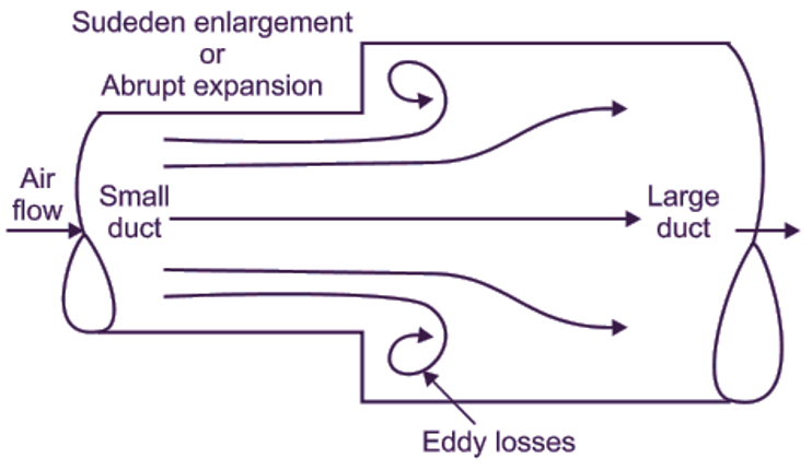
(a) Loss due to sudden enlargement
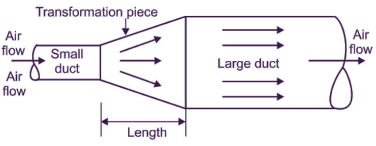
(b) Remedy using a transformation piece
Fig. 5
Loss due to sudden contraction
When the flow (sectional) area of pipe suddenly contracts, the flow area of air is reduced to large extent immediately after contraction. Refer the Section (1) – (1) called as ‘vena contracta’ in Fig. 6 (a). The flow area again increases and become equal to crosssectional area of pipe. Here, the loss due to change in velocty is not due to sudden contract on, but due to sudden enlargement at section 2-2. To reduce the loss, the duct is designed as shown in Fig. 6 (b).
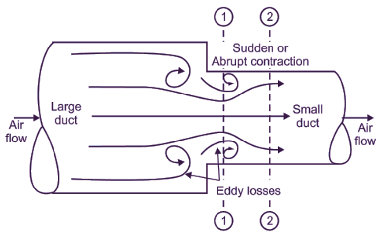
(a) Loss due to sudden contraction

(b) Remedy using a transformation piece
Fig. 6
Losses due to elbows
To reduce the losses due to change in direction of air, the elbows should be properly designed and fabricated. In designing the ducts, radius ratio and aspect ratio have great importance.
Loss due to heat transfer
When cooled air is passed to conditioned space, it exchanges heat energy with the surrounding. This may increase the cooling load on the coil. Therefore, duct must be insulated.