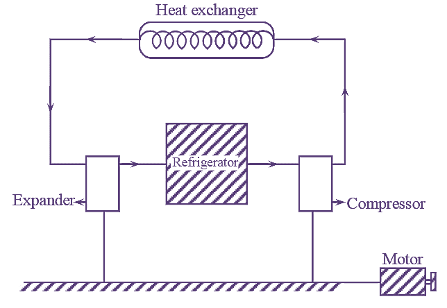
The ideal reversed Carnot cycle is modified to obtain Bell Coleman cycle. This is done to improve the COP of reversed Carnot cycle either by reducing the temperature of hot body or increasing the temperature of cold body. The figure 1 shows the components of Bell Coleman cycle.

Figure 1: Bell Coleman Cycle.
COP for Bell Coleman air-refrigerator


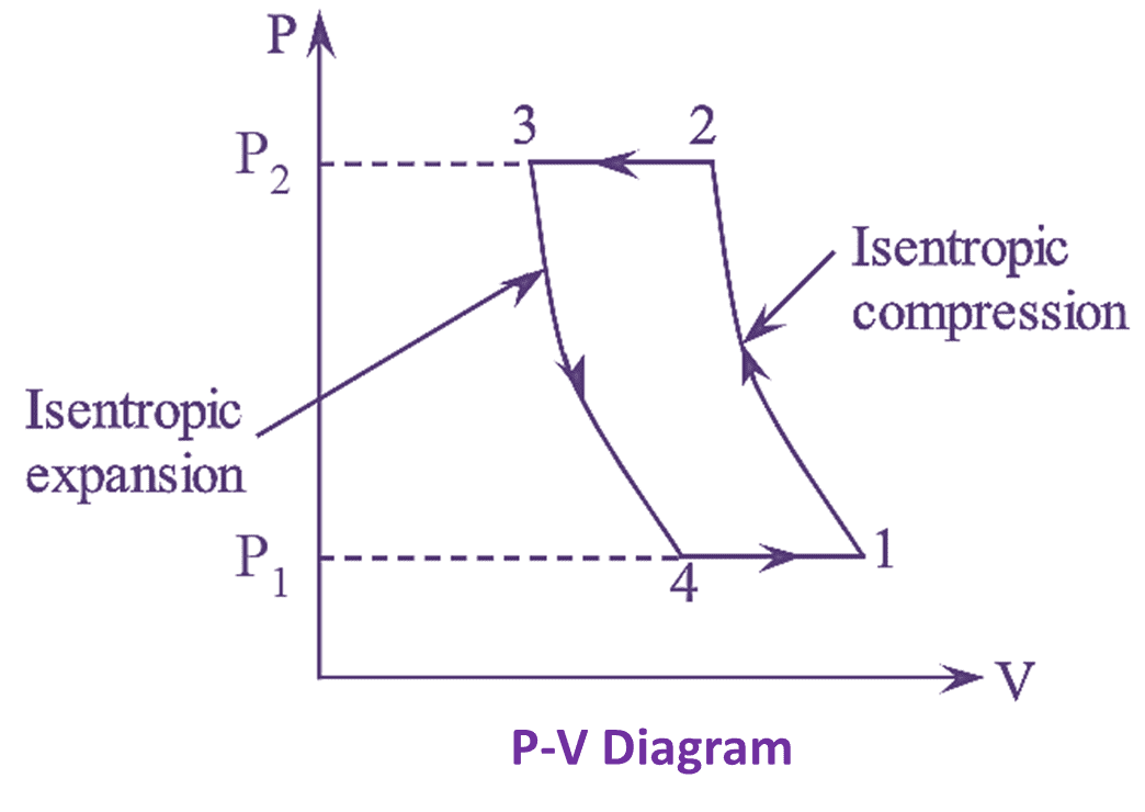
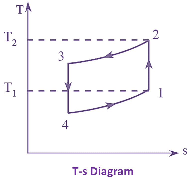
Figure 1: Bell Coleman Cycle on P-V and T-s Diagrams.
Isentropic Compression Process
The cold air from the refrigerator is drawn into the compressor cylinder where it is compressed isentropically. During the compression stroke, pressure and temperature increases from P1 to P2 and T1 to T2 whereas volume decreases from V1 to V2.
Constant Pressure Cooling Process
The warm air from the compressor is then passed into the heat exchanger (or) cooler where it is cooled with the help of cooling medium i.e., water, at constant pressure. The temperature and volume decrease from T2 to T3 and V2 to V3 whereas pressure remains constant.
Isentropic Expansion Process
The air from the heat exchanger is now drawn into the expander cylinder where it is expanded isentropically. Pressure and temperature decrease from P3 to P4 and T3 to T4 respectively, whereas volume increases from V3 to V4.
Constant Pressure Expansion Process
The cold air from the expander is now passed to the refrigerator where it is expanded at constant pressure. The temperature and volume increase from T4 to T1 and V4 to V1 whereas pressure remains constant.
COP for Bell Coleman Air Refrigeration Cycle
Consider,
C – Specific heat at constant pressure.
COP is given by,
\[COP=\frac{R}{W}\]
Where,
R – Refrigeration effect
W – Workdone or work supplied.
Refrigeration effect,
\[R={{C}_{p}}({{T}_{1}}-{{T}_{4}})\text{ KJ/kg}\]
Work supplied,
W= Heat rejected – Heat absorbed
\[={{C}_{p}}({{T}_{2}}-{{T}_{3}})-{{C}_{p}}({{T}_{1}}-{{T}_{4}})\]
\[COP=\frac{{{C}_{p}}({{T}_{1}}-{{T}_{4}})}{{{C}_{p}}({{T}_{2}}-{{T}_{3}})-{{C}_{p}}({{T}_{1}}-{{T}_{4}})}\]
\[COP=\frac{({{T}_{1}}-{{T}_{4}})}{({{T}_{2}}-{{T}_{3}})-({{T}_{1}}-{{T}_{4}})}…(1)\]
For adiabatic compression,
\[\frac{{{T}_{1}}}{{{T}_{2}}}={{\left( \frac{{{P}_{2}}}{{{P}_{1}}} \right)}^{\frac{\gamma -1}{\gamma }}}…(2)\]
For adiabatic expansion,
\[\frac{{{T}_{3}}}{{{T}_{4}}}={{\left( \frac{{{P}_{3}}}{{{P}_{4}}} \right)}^{\frac{\gamma -1}{\gamma }}}={{\left( \frac{{{P}_{2}}}{{{P}_{1}}} \right)}^{\frac{\gamma -1}{\gamma }}}…(3)\]
Since, for constant pressure process, P3 = P2 and P4 = P1.
From equation (2) and (3)
\[\frac{{{T}_{2}}}{{{T}_{1}}}=\frac{{{T}_{3}}}{{{T}_{4}}}\]
Or
\[{{T}_{2}}={{T}_{1}}\times \frac{{{T}_{3}}}{{{T}_{4}}}\]
\[COP=\frac{({{T}_{1}}-{{T}_{4}})}{({{T}_{1}}.\frac{{{T}_{3}}}{{{T}_{4}}}-{{T}_{3}})-({{T}_{1}}-{{T}_{4}})}\]
\[=\frac{({{T}_{1}}-{{T}_{4}})}{\frac{{{T}_{3}}}{{{T}_{4}}}({{T}_{1}}-{{T}_{4}})-({{T}_{1}}-{{T}_{4}})}\]
\[=\frac{{{T}_{4}}({{T}_{1}}-{{T}_{4}})}{({{T}_{1}}-{{T}_{4}})-({{T}_{3}}-{{T}_{4}})}\]
\[COP=\frac{{{T}_{4}}}{{{T}_{3}}-{{T}_{4}}}\]
Advantages of Bell Coleman Air Refrigeration Cycle
- Refrigerant used is air, which is free of cost.
- Safe operation in NH3 machine is possible. Since, air is non-flammable.
- In aircrafts, the selection of system depends on the ratio of weight of air refrigeration system to toil of refrigeration. This ratio is too smaller than that of other refrigeration systems.
- Small amount of air leakage is permissible.
- There is no need of extra space of extra compressor because the compression of air source is handled by the maul compressor.
Disadvantages of Bell Coleman Air Refrigeration Cycle
- It requires more quantity of air to be circulated, when compared to other refrigerants.
- It has low COP value.
- Operating costs are higher.