Otto cycle is the ideal cycle for petrol and gas engines. It is also known as constant volume air cycle. This cycle consists of four processes. They are,
- Reversible adiabatic compression
- Constant volume heat addition process
- Reversible adiabatic expansion
- Constant volume heat rejection process.
The P-V and T-s diagrams of the cycle (see Figure 1),
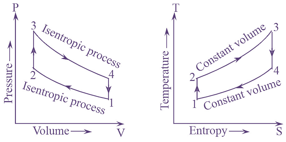
Figure 1: Otto Cycle.
Process 1-2: It is a reversible adiabatic compression process. During this process (lie air in the cylinder is compressed such that there is no heat transfer. Iii this process, the temperature increases from T1 to T2.
Process 2-3: It is a constant volume heat addition process. During this process, the compressed air in the cylinder is heated by means of a source. As the heat is supplied, the temperature increases to T3.
Process 3-4: It is reversible adiabatic expansion process. Due to the supply of heat, the temperature of air increases and starts to expanding without any heat transfer. The change in entropy in this process is zero and the temperature reduces to T4.
Process 4-1: This process is constant volume heat rejection process. After expanding, the hot air rejects heat to the sink at constant volume. This completes the cycle and it is repeated.
The workdone and efficiency of Otto cycle is calculated as follows.
Heat supplied during process ‘2 – 3’.
QS = CV (T3 – T2)
Heat rejected during process ‘4 – 1’.
QR= CV (T4 – T1)
Workdone per kg of air,
\[W={{Q}_{S}}-{{Q}_{R}}\]
\[={{C}_{V}}({{T}_{3}}-{{T}_{2}})-{{C}_{V}}({{T}_{4}}-{{T}_{1}})\]
Air standard effciency,
\[\eta =\frac{Workdone}{Heat\text{ }Supplied}\]
\[=\frac{W}{{{Q}_{S}}}\]
\[=\frac{{{C}_{V}}({{T}_{3}}-{{T}_{2}})-{{C}_{V}}({{T}_{4}}-{{T}_{1}})}{{{C}_{V}}({{T}_{3}}-{{T}_{2}})}\]
\[=1-\frac{({{T}_{4}}-{{T}_{1}})}{({{T}_{3}}-{{T}_{2}})}\]
\[=1-\frac{{{T}_{1}}\left[ \frac{{{T}_{4}}}{{{T}_{1}}}-1 \right]}{{{T}_{2}}\left[ \frac{{{T}_{3}}}{{{T}_{2}}}-1 \right]}…(1)\]
Since process ‘1-2’ and ‘3-4’ are isentropic.
\[\frac{{{T}_{2}}}{{{T}_{1}}}={{\left( \frac{{{V}_{1}}}{{{V}_{2}}} \right)}^{\gamma -1}}={{r}^{\gamma -1}}…(2)\]
\[{{T}_{2}}={{T}_{1}}\text{ }{{r}^{\gamma -1}}\]
And
\[\frac{{{T}_{3}}}{{{T}_{4}}}={{\left( \frac{{{V}_{4}}}{{{V}_{3}}} \right)}^{\gamma -1}}={{r}^{\gamma -1}}…(3)\]
\[{{T}_{4}}=\frac{{{T}_{3}}}{{{r}^{\gamma -1}}}\]
Where,
\[r=\frac{{{V}_{1}}}{{{V}_{2}}}=\frac{{{V}_{4}}}{{{V}_{3}}}\]
r known as as compression ratio
From equations (2) and (3),
\[\frac{{{T}_{2}}}{{{T}_{1}}}=\frac{{{T}_{3}}}{{{T}_{4}}}\frac{{{T}_{4}}}{{{T}_{1}}}=\frac{{{T}_{3}}}{{{T}_{2}}}\]
From equation (1),
\[{{\eta }_{a}}=1-\frac{{{T}_{1}}}{{{T}_{2}}}\]
Also,
\[\text{ }\frac{{{T}_{1}}}{{{T}_{2}}}={{r}^{\gamma -1}}\]
Hence,
\[{{\eta }_{a}}=1-\frac{1}{{{r}^{\gamma -1}}}\]
Since ‘γ’ is constant for air, the efficiency of Otto cycle depends on compression ratio and is independent of temperatures. The efficiency can be improved by increasing the compression ratio upto a certain limit. Beyond that limit, the increase in efficiency is considerably low and also leads to detonation.
Mean effective Pressure of Otto Cycle
The net workdone per kg in the otto cycle is given as,
W = Work during expansion – Work during compression.
\[={{W}_{3-4}}-{{W}_{1-2}}\]
\[=\frac{{{P}_{3}}{{V}_{3}}-{{P}_{4}}{{V}_{4}}}{\gamma -1}-\frac{{{P}_{2}}{{V}_{2}}-{{P}_{1}}{{V}_{1}}}{\gamma -1}\]
From isentropic relations,
\[\frac{{{P}_{3}}}{{{P}_{4}}}=\frac{{{P}_{2}}}{{{P}_{1}}}={{\left( \frac{{{V}_{1}}}{{{V}_{2}}} \right)}^{\gamma }}={{r}^{\gamma }}\]
And, pressure ratio
\[{{r}_{P}}=\frac{{{P}_{3}}}{{{P}_{2}}}=\frac{{{P}_{4}}}{{{P}_{1}}}\]
Since,
\[r=\frac{{{V}_{1}}}{{{V}_{2}}}=\frac{{{V}_{4}}}{{{V}_{3}}}\]
\[{{V}_{1}}=r{{V}_{2}}={{V}_{4}}=r{{V}_{3}}\]
\[W=\frac{1}{\gamma -1}\left[ {{P}_{4}}{{V}_{4}}\left( \frac{{{P}_{3}}{{V}_{3}}}{{{P}_{4}}{{V}_{4}}}-1 \right)-{{P}_{1}}{{V}_{1}}\left( \frac{{{P}_{2}}{{V}_{2}}}{{{P}_{1}}{{V}_{1}}}-1 \right) \right]\]
\[=\frac{1}{\gamma -1}\left[ {{P}_{4}}{{V}_{4}}\left( \frac{{{P}_{3}}}{{{P}_{4}}}.\frac{1}{r}-1 \right)-{{P}_{1}}{{V}_{1}}\left( \frac{{{P}_{2}}}{{{P}_{1}}}.\frac{1}{r}-1 \right) \right]\]
\[=\frac{1}{\gamma -1}\left[ {{P}_{4}}{{V}_{4}}\left( {{r}^{\gamma }}.\frac{1}{r}-1 \right)-{{P}_{1}}{{V}_{1}}\left( {{r}^{\gamma }}.\frac{1}{r}-1 \right) \right]\]
\[=\frac{1}{\gamma -1}\left[ {{P}_{4}}{{V}_{4}}\left( {{r}^{\gamma -1}}-1 \right)-{{P}_{1}}{{V}_{1}}\left( {{r}^{\gamma -1}}-1 \right) \right]\]
Also,
\[{{V}_{1}}={{V}_{4}}\]
\[W=\frac{{{V}_{1}}}{\gamma -1}\left[ {{P}_{4}}\left( {{r}^{\gamma -1}}-1 \right)-{{P}_{1}}\left( {{r}^{\gamma -1}}-1 \right) \right]\]
\[=\frac{{{V}_{1}}}{\gamma -1}\left[ \left( {{r}^{\gamma -1}}-1 \right)\left( {{P}_{4}}-{{P}_{1}} \right) \right]\]
\[=\frac{{{P}_{1}}{{V}_{1}}}{\gamma -1}\left[ \left( {{r}^{\gamma -1}}-1 \right)\left( \frac{{{P}_{4}}}{{{P}_{1}}}-1 \right) \right]\]
\[=\frac{{{P}_{1}}{{V}_{1}}}{\gamma -1}\left[ \left( {{r}^{\gamma -1}}-1 \right)\left( {{r}_{p}}-1 \right) \right]\]
Mean effective pressure is given as,
\[MEP=\frac{Work\text{ }done}{Swept\text{b}Volume}\]
\[=\frac{\frac{{{P}_{1}}{{V}_{1}}}{\gamma -1}\left[ \left( {{r}^{\gamma -1}}-1 \right)\left( {{r}_{p}}-1 \right) \right]}{{{V}_{1}}-{{V}_{2}}}\]
\[=\frac{\frac{{{P}_{1}}{{V}_{1}}}{\gamma -1}\left[ \left( {{r}^{\gamma -1}}-1 \right)\left( {{r}_{p}}-1 \right) \right]}{{{V}_{1}}\left[ 1-\frac{{{V}_{2}}}{{{V}_{1}}} \right]}\]
\[=\frac{\frac{{{P}_{1}}{{V}_{1}}}{\gamma -1}\left[ \left( {{r}^{\gamma -1}}-1 \right)\left( {{r}_{p}}-1 \right) \right]}{{{V}_{1}}\left[ 1-\frac{1}{r} \right]}\]
Therefore,
\[ MEP=\frac{{{P}_{1}}r\left[ \left( {{r}^{\gamma -1}}-1 \right)\left( {{r}_{p}}-1 \right) \right]}{\left( \gamma -1 \right)\left( r-1 \right)}\]
Differences Between Otto cycle and Diesel cycle
| Otto cycle | Diesel cycle |
| 1. In this cycle, heat is added at constant volume. | 1. In this cycle, heat is added at constant pressure. |
| 2. Efficiency is higher than diesel cycle for same | 2. Efficiency is lower than otto cycle, compression ratio. |
| 3. Ideal for spark ignition engines. | 3. Ideal for compression ignition engines. |
| 4. Applications: Gas turbines, petrol engines, gas engines. | 4. Applications: Submarines. Ships, locomotives, trucks, light oil engines, combustion engines, heavy duty equipment, and electronic power plants. |