Rankine cycle is an ideal thermodynamic cycle for thermal power plants. In this cycle all processes are reversible and it produces useflul work by expansion of steam. Rankine cycle is a modified Carnot cycle, in which most of the limitations of carnot cycle are eliminated. A schematic diagram of ideal Rankine cycle is shown in figure (1).
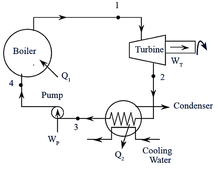
Figure 1: Rankine Cycle.
Components of Rankine Cycle
A Rankine cycle consists of a boiler, turbine, condenser and a pump.
Boiler
In boiler, heat is transferred to the feed water from an external source to generate the steam. Heat may be produced by burning of coal or other fossil fuels. This high pressure and high temperature steam is supplied to the turbine for expansion process.
Turbine
In turbine, high pressure and high temperature steam expands to produce mechanical work (shaft work). Then this expanded steam is passed to the condenser.
Condenser
It is an heat exchanger, in which the steam condenses into water by rejecting heat to cooling water which is continuously circulated. The water is pumped to the boiler with the help of feed pump. It also maintains a low pressure at the turbine exit.
Feed Pump
It is used to recirculate the water from condenser to the boiler. Work required to run the feed pinup is relatively small in comparison with work produced by the turbine, even it is negligible for low boiler pressures.
Working of Rankine Cycle
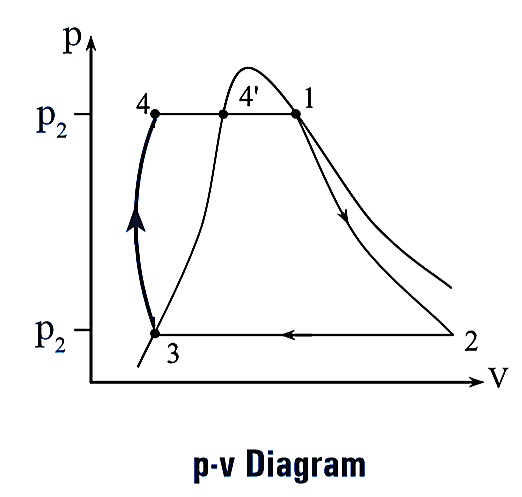
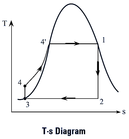
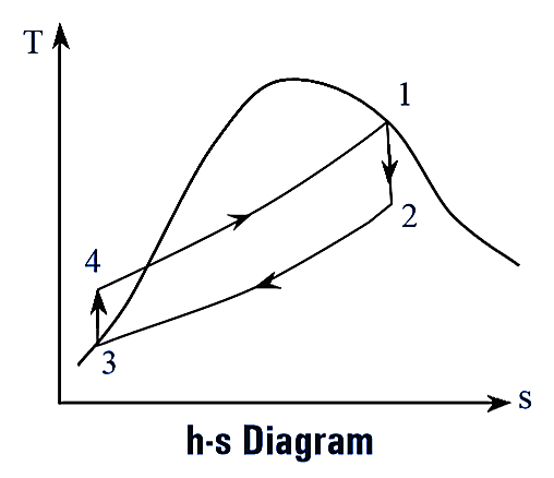
Figure 2.
The p-v, T-s and h-s diagrams of Rankine cycle are shown in figure (2). This cycle is completed in following four processes. They are,
- Reversible adiabatic expansion (Process 1-2)
- Constant pressure heat rejection (Process 2-3)
- Reversible adiabatic compression (Process 3-4)
- Constant pressure heat addition (Process 4-1)
Reversible Adiabatic Expansion
This process is represented on thermodynamic cycle as process 1-2. During this process, the steam expands isentropically (i.e., entropy remains constant) in turbine from pressure p1 to p2. This process is also called “Isentropic expansion process”.
Constant Pressure Heat Rejection
The process 2-3 on thermodynamic cycle represents the heat rejection at constant pressure. During this process, the steam is isothermally condensed to saturated water in condenser by rejecting heat to the surroundings (generally, cooling water is continuously circulated for heat rejection). This process is also known as “Isobaric process”.
Reversible Adiabatic Compression
This process is represented by process 3-4 on thermodynamic cycle. During this process, the water at condenser pressure (p3) is pumped to the boiler by feed pump, and the pressure of water increased to boiler pressure (p4). This process is reversible and adiabatic.
Constant Pressure Heat Addition
The process 4-1 represents the constant pressure heat addition. During this process, the water is heated in the boiler at constant pressure from state 4 to state 1 to produce steam.
Efficiency of Rankine Cycle
Consider 1 kg of steam is supplied to the Rankine cycle, then by applying steady flow energy equation (S.F.E.E) to the boiler, turbine, condenser and pump.
(i) For Boiler
\[{{h}_{4}}+\text{ }{{Q}_{1}}=\text{ }{{h}_{1}}\].
∴ Heat supplied in boiler, ${{Q}_{1}}=\text{ }{{h}_{1}}-\text{ }{{h}_{4}}$
(ii) For Turbine
\[{{h}_{1}}=\text{ }{{h}_{2}}+\text{ }{{W}_{T}}\text{ }\]
∴ Turbine work, ${{W}_{T}}=\text{ }{{h}_{1}}-\text{ }{{h}_{2}}$
(iii) For condenser
\[{{h}_{2}}+\text{ }{{Q}_{2}}=\text{ }{{h}_{3}}\]
∴ Heat rejected in condenser, ${{Q}_{2}}=\text{ }{{h}_{2}}-\text{ }{{h}_{3}}$
(iv) For Feed pump
\[{{h}_{3}}+\text{ }{{W}_{p}}=\text{ }{{h}_{4}}\]
∴ Work supplied to the feed pump, ${{W}_{p}}=\text{ }{{h}_{4}}-\text{ }{{h}_{3}}$
Since the water is incompressible, the change in density and specific volume are negligible For reversible adiabatic compression.
\[Tds=\text{ }dh-\text{ }vdp\]
For isentropic process ds = 0
\[0=\text{ }dh-\text{ }vdp\]
\[\int\limits_{3}^{4}{dh}=\text{ }v\int\limits_{3}^{4}{dp}\]
\[({{h}_{4}}-\text{ }{{h}_{3}})=\text{ }v\text{(}{{p}_{3}}-\text{ }{{p}_{4}})\]
Also,
\[{{W}_{P}}=\text{ }({{h}_{4}}-\text{ }{{h}_{1}})=\text{ }v\text{(}{{p}_{3}}-\text{ }{{p}_{4}})\]
Now, the efficiency of Rankine cycle,
\[{{\eta }_{g}}=\frac{\text{Work output}}{\text{Heat supplied}}\]
\[=\text{ }\frac{{{W}_{T}}-\text{ }{{W}_{P}}}{{{W}_{1}}}\]
\[=\text{ }\frac{\text{(}{{h}_{1}}-\text{ }{{h}_{2}})\text{ }-\text{ (}{{h}_{4}}-\text{ }{{h}_{3}})}{\text{(}{{h}_{1}}-\text{ }{{h}_{4}})}\]
Since, WT >> Wp, pump work can be neglected. Then,
\[{{\eta }_{g}}=\text{ }\frac{{{h}_{1}}-\text{ }{{h}_{2}}}{{{h}_{1}}-\text{ }{{h}_{4}}}\text{ or }\frac{{{h}_{1}}-\text{ }{{h}_{2}}}{{{h}_{1}}-\text{ }{{h}_{3}}}\]