In this topic, you study Brushless DC Motor – Working, Diagram & Construction.

Working of Brushless DC Motor

With the advent of variable frequency inverters, it has become possible to free the synchronous motors from the fixed-speed constraint imposed by mains-frequency operation. Inverter-fed self-controlled permanent magnet synchronous motor is one such motor. There being overall similarity between this motor (which is basically an a.c. motor) and conventional dc motor except the requirement of brushes and the commutator, it is named as brushless or commutator less dc motor.
Constructional Features of Brushless DC Motor

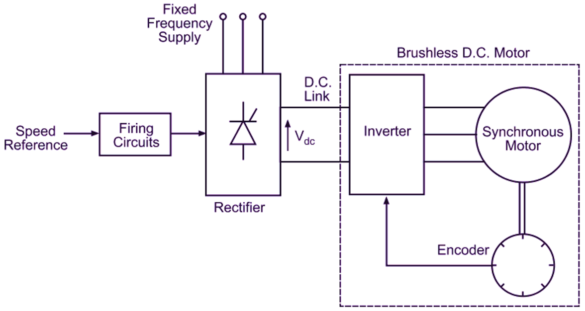
Fig. 1: Brushless dc motor drive.
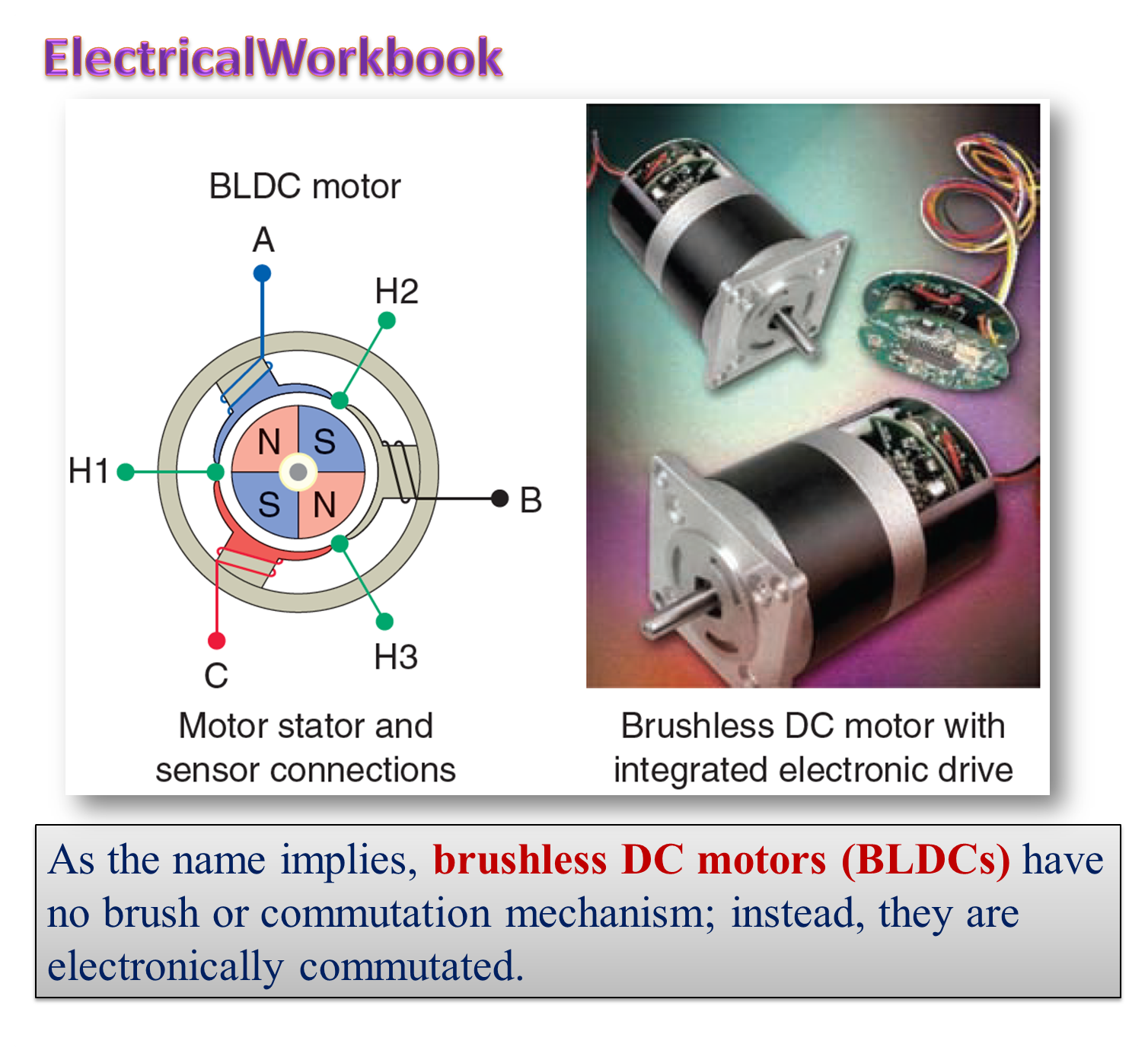
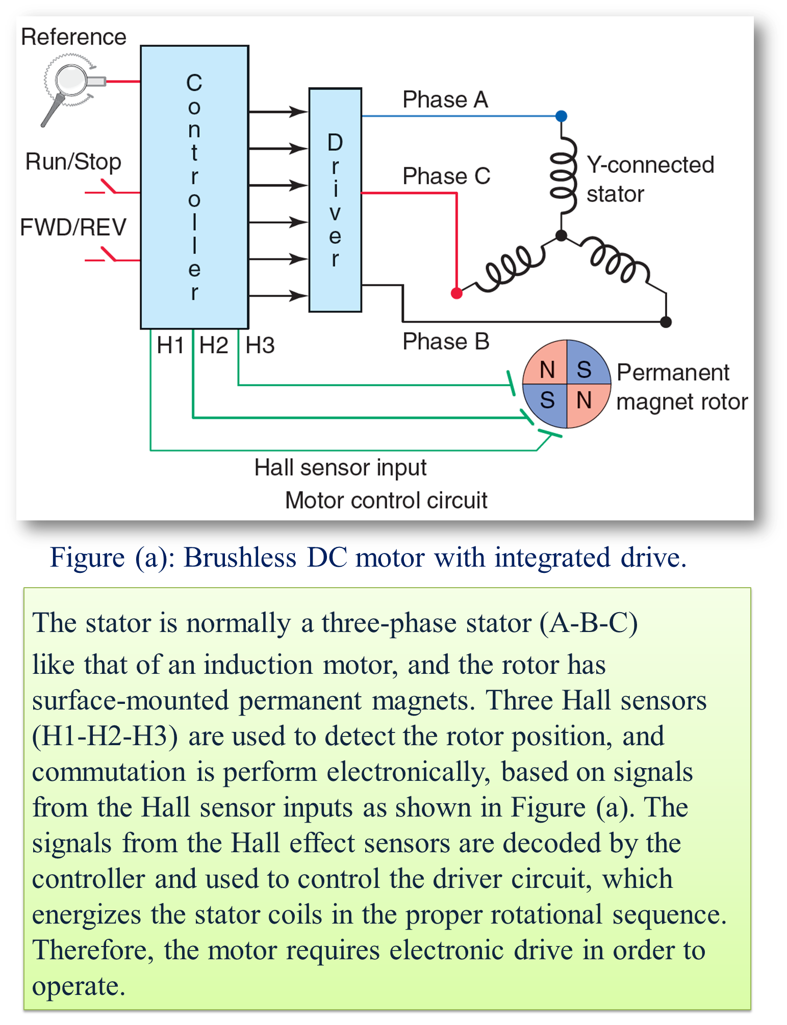
Fig. 1 illustrates this type of motor with the help of a simple block diagram. In conventional d.c motor, field magnets are placed on the stator and armature winding is placed on the rotor. However, brushless dc motor has a polyphase winding (armature) on the stator and permanent magnets on the rotor. The motor is fed through a rectifier, dc link and inverter. Either an optical or Hall element sensor (encoder)is suitably mounted on the rotor shaft.
Principle of Operation of Brushless DC Motor
The drive functions similar to dc motor. In a dc motor, we know that the mechanical commutator reverses the direction of the current in each (rotating)armature coil at the appropriate point such that, regardless of speed, the current under each(stationary) field pole is always in the right direction to produce the desired unidirectional torque. In a brushless dc motor, the roles of stator and rotor are reversed i.e. in the case of this motor, the field is rotating and the armature winding consisting of three phases is stationary. The timing and direction of current in each phase is governed by the inverter switching which in turn is determined by the rotor position-dependent signals obtained from an encoder mounted on the rotor shaft. Hence, regardless of speed, the torque is always in the right direction. Thus, the combination of the rotor position sensor and inverter performs effectively the same function as the commutator in a conventional dc motor. Hence, such a motor is also sometimes referred to as an electronically commutated motor.
Operating Characteristics of BLDC Motor
Speed-torque characteristics of brushless dc motor are similar to the conventional dc motor.
Speed Control of BLDC Motor
The speed of brushless dc motor can be controlled by controlling the dc link voltage to the inverter. The dc link is usually provided by a controlled rectifier. Hence, the motor speed can be controlled by varying the input converter firing angle as illustrated in Fig. 1.
Applications of BLDC Motor
Due to absence of brushes and commutator, brushless dc motors require practically no maintenance, have long life, high reliability, high efficiency (exceeding 75
The brushless dc motors are used in numerous applications which include turn table drives in record players, tape drives for video recorders, spindle drives in hard disc drives for computers, lower cost and low power drives in computer peripherals, instruments and control systems. They are also used in the fields of aerospace (e.g. gyroscope motors) and biomedical (e.g. in cryogenic coolers and artificial heart pumps).