In this topic, you study Types of DC Generators – Working, Diagram & Construction.
In almost all the practical dc generators, the magnetic field is produced by electromagnetic means i.e. by using field poles. The direct current necessary to energise the field poles is called the exciting current. Depending upon the way in which the field windings are supplied with exciting current, the dc generators are classified into following two basic categories.
Separately Excited DC Generators
If the field winding of a generator is supplied with exciting current from an external dc source such as a battery, another generator or indeed any suitable dc supply, then such a generator is said to be separately excited. Fig. 1 shows diagrammatically the separately excited generator using battery for the supply of field current. In this diagram, F-FF represents the field winding and A-AA the armature. The field winding of a separately excited generator normally has a large number of turns of fairly thin wire and hence the high resistance in order to limit the field current to a small value. This is helpful in reducing the power loss in the field circuit. It should be remembered that when the required flux is to be produced with small current, the number of turns required for the winding is obviously large.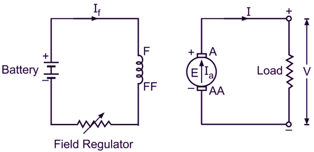
Fig. 1: Schematic representation of a separately excited dc generator
Self-Excited DC Generators
If the field winding of a generator is supplied with the exciting current from the armature of the generator itself, it is said to be self-excited. In the normal condition, the field poles of such a generator always possess some residual or remanent magnetism. This enables the armature to generate small emf initially when the generator is started. This emf circulates small amount of current through the field winding thereby the original residual flux is strengthened and more emf is produced. This process being cumulative, ultimate generator voltage is built up to its full value. Based on the manner in which field winding is connected to the armature winding, the self-excited generators are further classified as follows :
DC Shunt Generators
When the field winding (Z-ZZ) is connected across the armature winding (A-AA) forming a parallel or shunt circuit, the generator is said to be a shunt generator (Fig. 2). The shunt field has a comparatively large number of turns of the fine gauge copper wire and hence the high resistance for the same reason as already discussed in the case of a separately excited generator.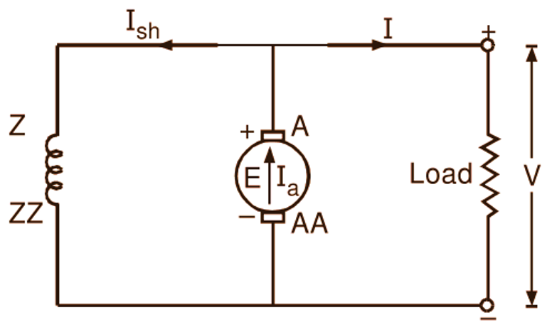
Fig. 2: Schematic representation of a dc shunt generator
DC Series Generators
In this type of a dc generator, the field winding (Y-YY) is connected in series with the armature winding (A-AA) as shown in Fig. 3. The series field winding Y-YY has comparatively few turns of thick copper wire (or strip) and consequently a low resistance. It should be noted that in this case, the field current being large (= load current), the required flux can be produced even with a small number of turns.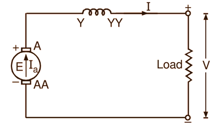
Fig. 3: Schematic representation of a dc series generator
DC Compound Generators
A compound generator is a combination of a series and a shunt generator. In this type of generator, both the shunt and series field windings are employed. The coils of both these windings are mounted on the same poles. If the series field winding (Y-YY) is connected in series with the armature winding (A-AA) and the shunt field winding (Z-ZZ) is connected across the armature only as illustrated in Fig. 4 (a), the generator is said to be a short-shunt compound generator. However, if the shunt field is connected across the armature and series field together as illustrated in Fig. 4 (b), the generator is called the long-shunt compound generator.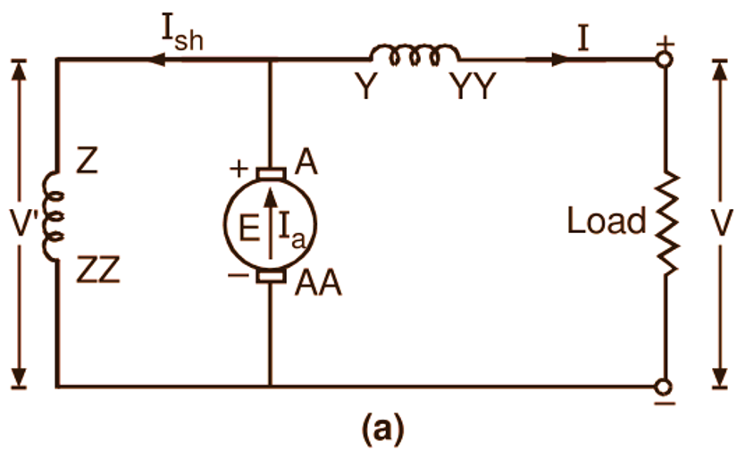
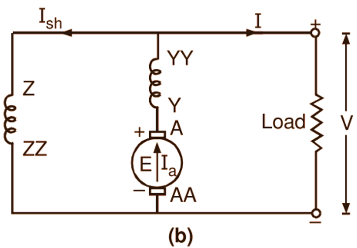
-
Fig. 4: Schematic representation of (a) a short-shunt compound generator, (b) a long-shunt compound generator