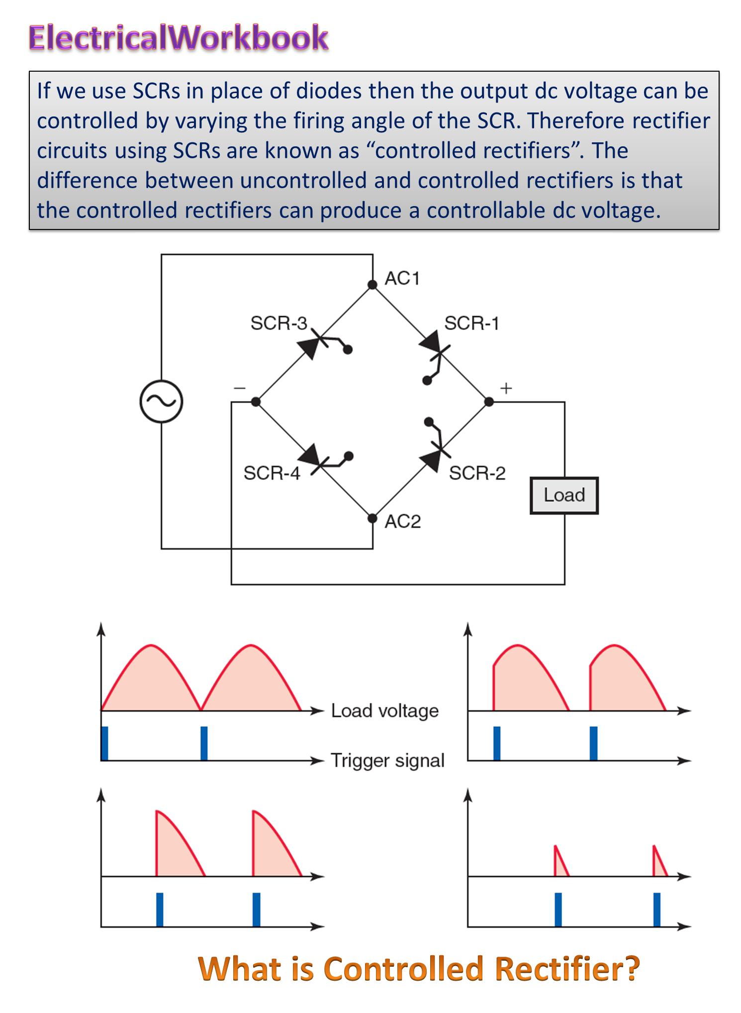
The diode rectifiers are used in many electronic circuits and systems to supply DC voltage. If the continuous control of output DC voltage is not required, then silicon diodes are used in the rectifier circuits. But when continuous control of output DC voltage is required in some electronic circuits and systems, the silicon diodes are not used but thyristors (SCRs) are used in place of diodes. This type of rectifier is called controlled rectifier. The rectifier which controls the output DC power delivered to the load as per its requirement is called a controlled rectifier. The SCRs are used in controlled rectifiers because of their superior performance than that of ordinary silicon diodes. The controlled rectifiers are used in many industrial applications such as traction systems, portable hand drives, light dimmer, fan speed regulator, etc. require controlled DC power.
Block Diagram of a Controlled Rectifier
The block diagram of a controlled rectifier is as shown in Fig. 1(a). The circuit symbol of a controlled rectifier is shown in Fig. 1(b). A conducting thyristor is turned off due to natural or line commutation. The ac mains voltage itself is used for commutating the thyristors, therefore these converters are known as line commutated converters (LCC).

Fig. 1: Controlled rectifier block diagram.
Classification of Controlled Rectifiers
The controlled rectifiers can also be classified broadly into two categories :
- Single-phase controlled rectifiers and
- Three-phase controlled rectifiers.
They can be further classified into different categories based on type of load i.e.
- Resistive (R),
- Resistive-inductive (RL) and
- Resistive-inductive-battery (RLE) loads.
Fig. 2 shows general classification of controlled rectifiers based on AC input voltage and DC output voltage.

Fig. 2: Classification of controlled rectifiers based on AC input voltage and DC output voltage
Fig. 3 shows the classification of controlled rectifiers based on type of load.

Fig. 3: Classification of controlled rectifiers based on type of load
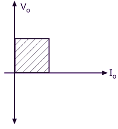
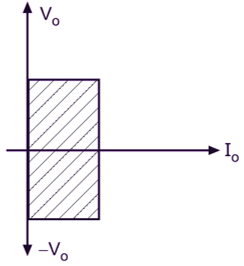
Full-wave phase-controlled rectifiers are sometimes classified into two categories: one-quadrant converter and two-quadrant converter based on the polarity of output voltage Vo and output current Io as shown in Fig. 4.

(a)

- (b)
Fig. 4: Controlled Rectifier (a) One-quadrant converter (b) Two-quadrant converter
Types of Controlled Rectifier
There are two types of controlled rectifiers. They are :
- Half (or semi) controlled rectifier.
- Full controlled rectifier.
Half Controlled Rectifier
Half controlled rectifier use combination of diodes and SCRs for rectification. A half controlled rectifier generally in the bridge configuration. There will be a saving in cost. The bridge consists of equal number of diodes and SCRs.
Full Controlled Rectifier
Full controlled rectifiers use only SCRs for rectification. A full controlled rectifier generally in the bridge configuration. The bridge consists of only SCRs and no diode is used.
Advantages of Controlled Rectifier
These converters are simple and less expensive, and the efficiency of rectification in general is above 95
Applications of Controlled Rectifier
Some applications of controlled rectifiers are :
- Light dimmer.
- AC fan speed regulator.
- AC motor speed control.
- AC voltage regulator.