After reading this Mesh Analysis topic of electric or network circuits, you will understand the theory and also able to apply it in numerical problems.
A mesh is a loop which does not contain any inner loop. Mesh analysis is only applicable to a planar network. A planar network is the one that can be drawn in a plane with no branches crossing one another.
Procedure (steps) for applying mesh analysis:
- Identify the total number of meshes.
- Assign the mesh currents.
- Develop the KVL equation for each mesh.
- Solve the equations to find the mesh currents.
Note:
- The total number of equations (e) required to solve the network with the help of mesh analysis is
e = b – (N – 1).
where, b is the total number of branches and N is the total number of nodes.
- The direction of mesh currents can be taken in any direction either clockwise or counter-clockwise. But clockwise direction results in a simpler analysis.
Examples
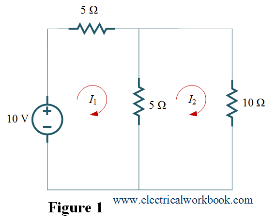
Example1. For the given network, find currents I1 and I2 using Mesh analysis.

Solution:
Let’s follow the Procedure for applying Mesh Analysis
Step 1: – The total number of meshes is 2.
Step 2: – The mesh currents I1 and I2 for mesh 1 and mesh 2 respectively as shown in Figure 1.
Step 3 and Step 4: – Apply KVL to mesh 1 as shown in Figure 2,
$ – 10 + 5{I_1} + 5({I_1} – {I_2}) = 0$
$2{I_1} – {I_2} = 2$ ….(1)
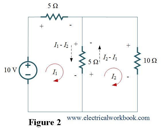
Apply KVL to mesh 2 as shown in Figure 2,
$10{I_2} + 5({I_2} – {I_1}) = 0$
$15{I_2} – 5{I_1} = 0$
${I_1} = 3{I_2}$ ….(2)
Put Eq.(2) in Eq.(1), we get
$5{I_2} = 2$
\[{I_2} = \frac{2}{5}\]
from Eq.(2)
\[{I_1} = 3\left( {\frac{2}{5}} \right){\text{ = }}\frac{{ 6}}{5}{\text{ A}}\]
Thus,
\[{I_2} = \frac{2}{5}{\text{ A}};{I_1} = \frac{{ 6}}{5}{\text{ A}}{\text{.}}\]
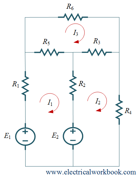
Example 2. For the given network, write Mesh equations.
Solution:
Let’s follow the Procedure for applying Mesh Analysis
Step 1: – The total number of meshes is 3.
Step 2: – The mesh currents I1, I2 and I3 for meshes 1, 2 and 3 are shown in Figure given in example 2.
Step 3: – Apply KVL to mesh 1,
$- {E_1} + {R_1}{I_1} + {R_2}({I_1} – {I_3}) + {R_3}({I_1} – {I_2}) = 0{\text{}}$
Apply KVL to mesh 2,
\[ – {E_2} + {R_3}({I_2} – {I_1}) + {R_4}({I_2} – {I_3}) + {R_4}{I_2} = 0{\text{ }}\]
Apply KVL to mesh 3,
\[{R_6}{I_3} + {R_4}({I_3} – {I_2}) + {R_2}({I_3} – {I_1}) = 0{\text{}}\]