In this topic, you study First Quadrant Chopper or Type A Chopper or Class A Chopper v-i plane, working principle, quadrant operation, Applications, and Circuit diagrams.
Type A chopper is basically a Step-Down Chopper.
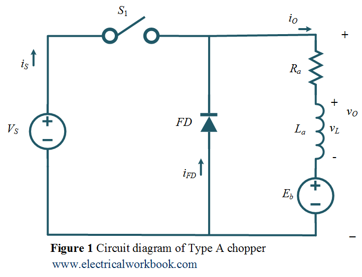
Circuit Diagram
The Type A chopper circuit diagram as shown in Figure 1. Here the motor load is assumed, Ra and La armature resistance and inductance of the motor respectively. Eb is the back emf of the motor.
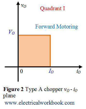
vO – iO plane
The Type A chopper operates in the first quadrant of vO – iO plane as shown in Figure 2. Here vO is the output voltage, VO is the average output voltage, iO is the output current and IO is the average output current of Type A chopper circuit.
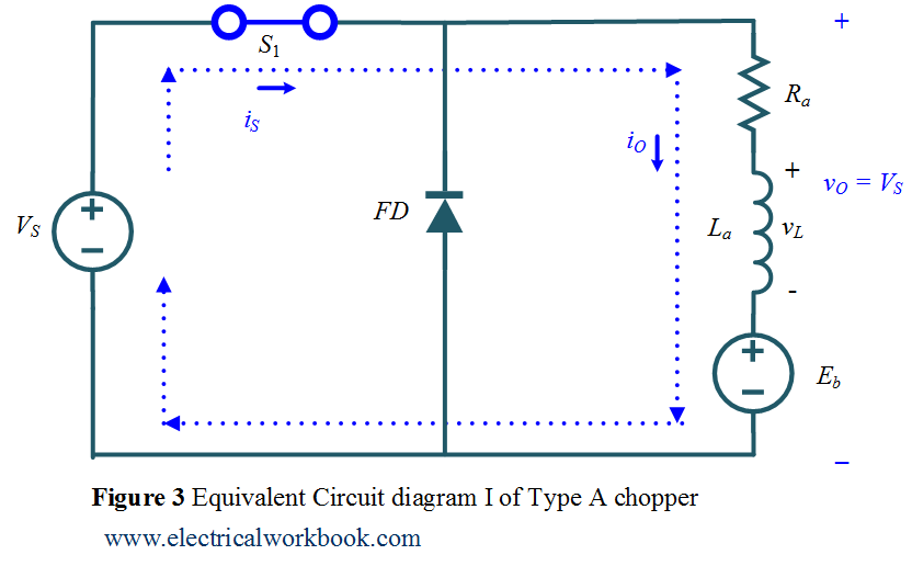
Quadrant I operation when Switch S1 turned on
The Type A chopper equivalent circuit diagram for Quadrant I is shown in Figure 3. Here switch S1 operated, Switch S1 conducts, output voltage vO and the output current iO both are positives, power flows from source to load and inductor stores energy, the motor rotates in the forward direction hence called forward motoring.
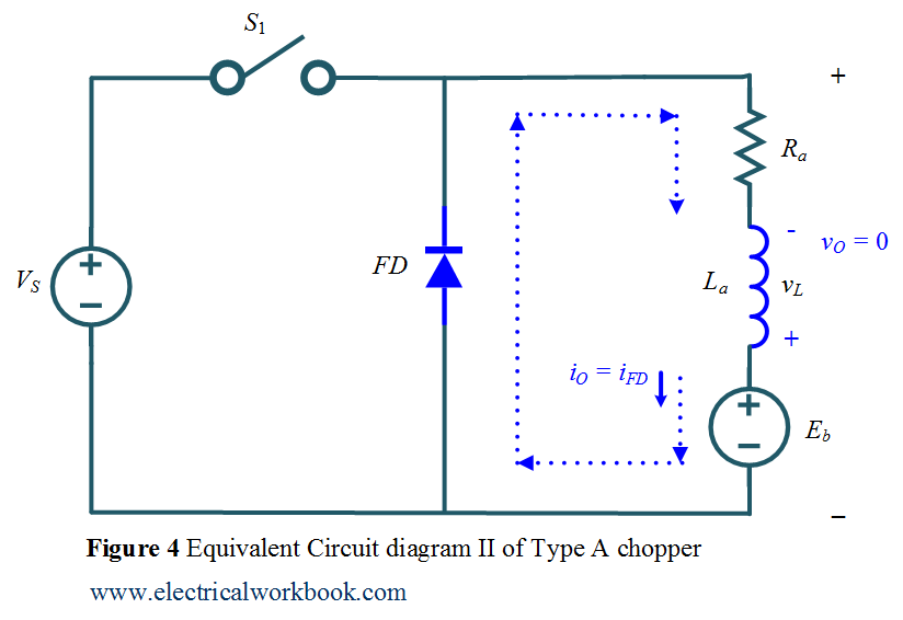
Quadrant I operation when Switch S1 turned off
The Type A chopper equivalent circuit diagram for Quadrant I is shown in Figure 4. Switch S1 turned off diode FD conducts, output current iO is positive and the output voltage vO becomes zero, inductor release energy and freewheeling action using diode FD takes place, the motor rotates in the forward direction hence called Forward motoring.
Application
This chopper is suitable for motoring application only.