In this topic, you study Four Quadrant Chopper or Type-E Chopper or Class E Chopper v-i plane, working principle, quadrant operation, and Circuit diagrams.
Type E chopper is a four-quadrant chopper.
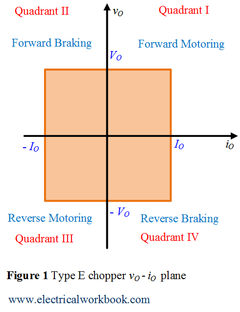
vO – iO plane
The Type E chopper operates in the four quadrants of vO – iO plane as shown in Figure 2. Here vO is the output voltage, VO is the average output voltage, iO is the output current and IO is the average output current of Type E chopper circuit.
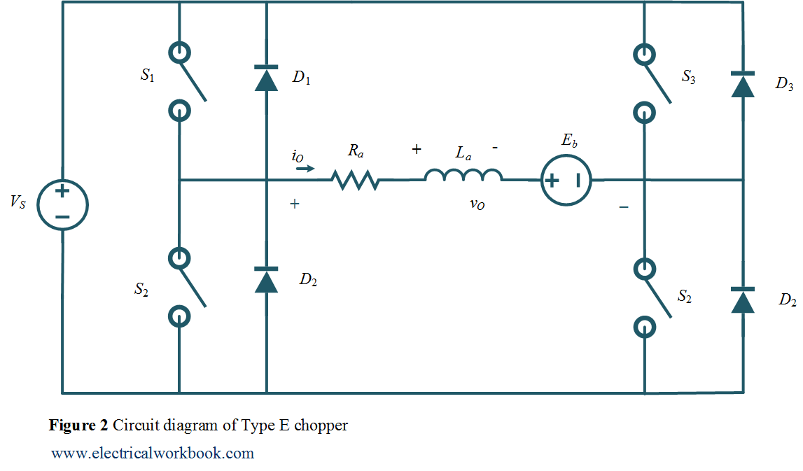
Circuit Diagram
The Type E chopper circuit diagram as shown in Figure 1. Here the motor load is assumed, Ra and La armature resistance and inductance of the motor respectively. Eb is the back emf of the motor.
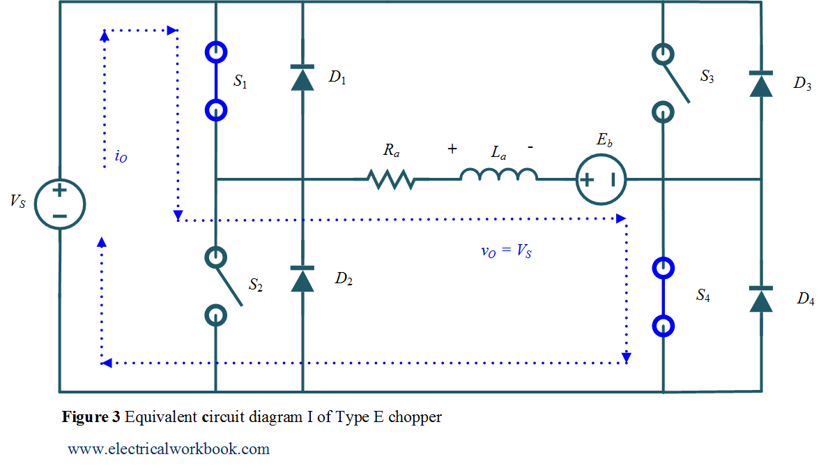
Quadrant I operation when Switch S1 turned on
The Type E chopper equivalent circuit diagram for Quadrant I is shown in Figure 3. Here switch S1 operated, Switches S1 and S4 conduct, output voltage vO and the output current iO both are positives, power flows from source to load and inductor stores energy, the motor rotates in the forward direction hence called forward motoring.
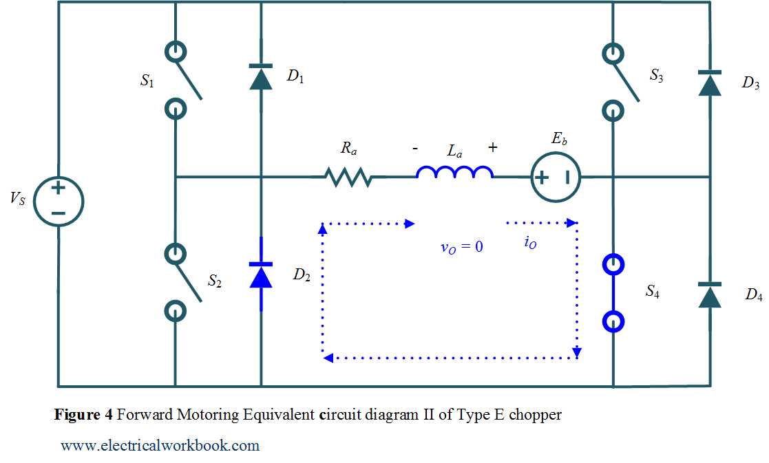
Quadrant I operation when Switch S1 turned off
The Type E chopper equivalent circuit diagram for Quadrant I is shown in Figure 4. Switch S1 turned off but switch S4 and diode D2 conducts, output current iO is positive and the output voltage vO becomes zero, inductor release energy and freewheeling action using diode D2 takes place, the motor rotates in the forward direction hence called Forward motoring.
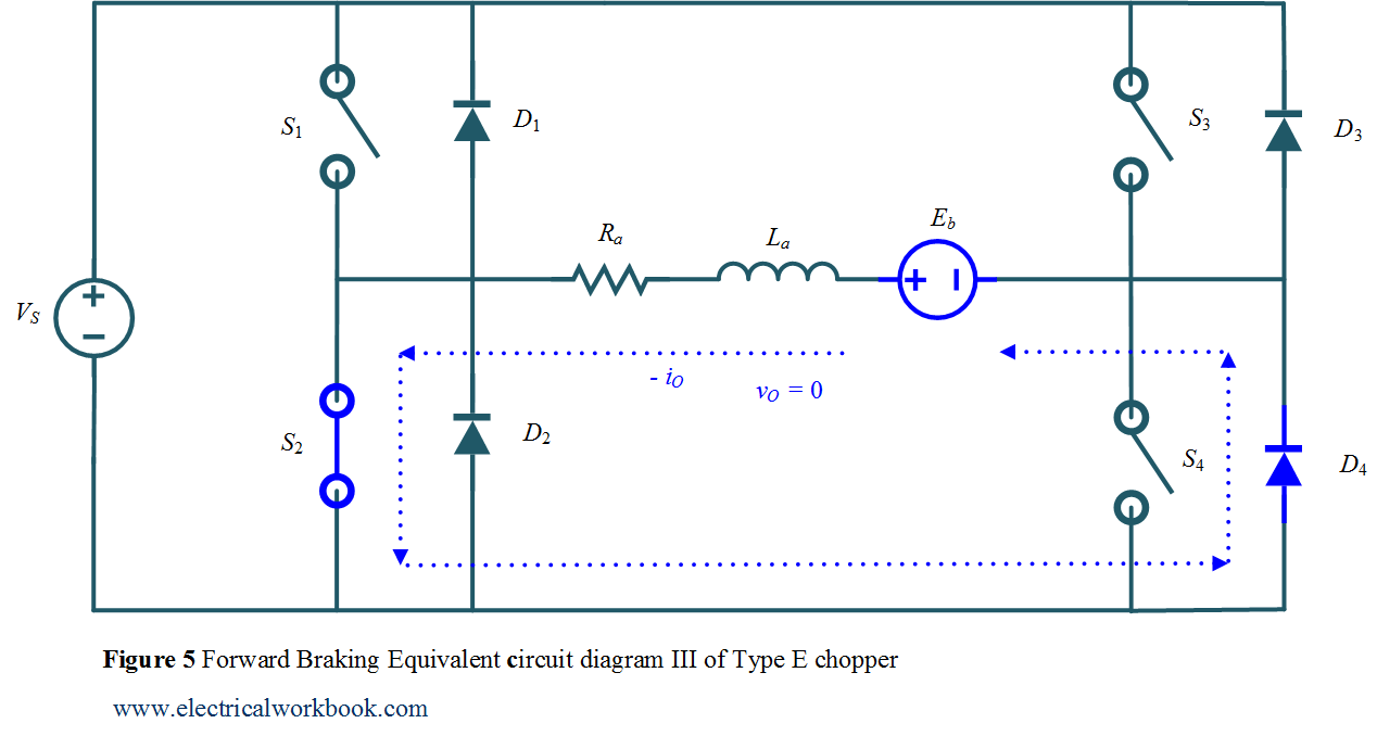
Quadrant II operation when Switch S2 turned on
The Type E chopper equivalent circuit diagram for Quadrant II is shown in Figure 5. Let us assume that the motor is running in the forward direction. Here switch S2 operated, Switch S2 and diode D4 conducts, output voltage vO is zero and Eb is responsible for the negative output current iO, machine behave as generator and inductor stores energy.
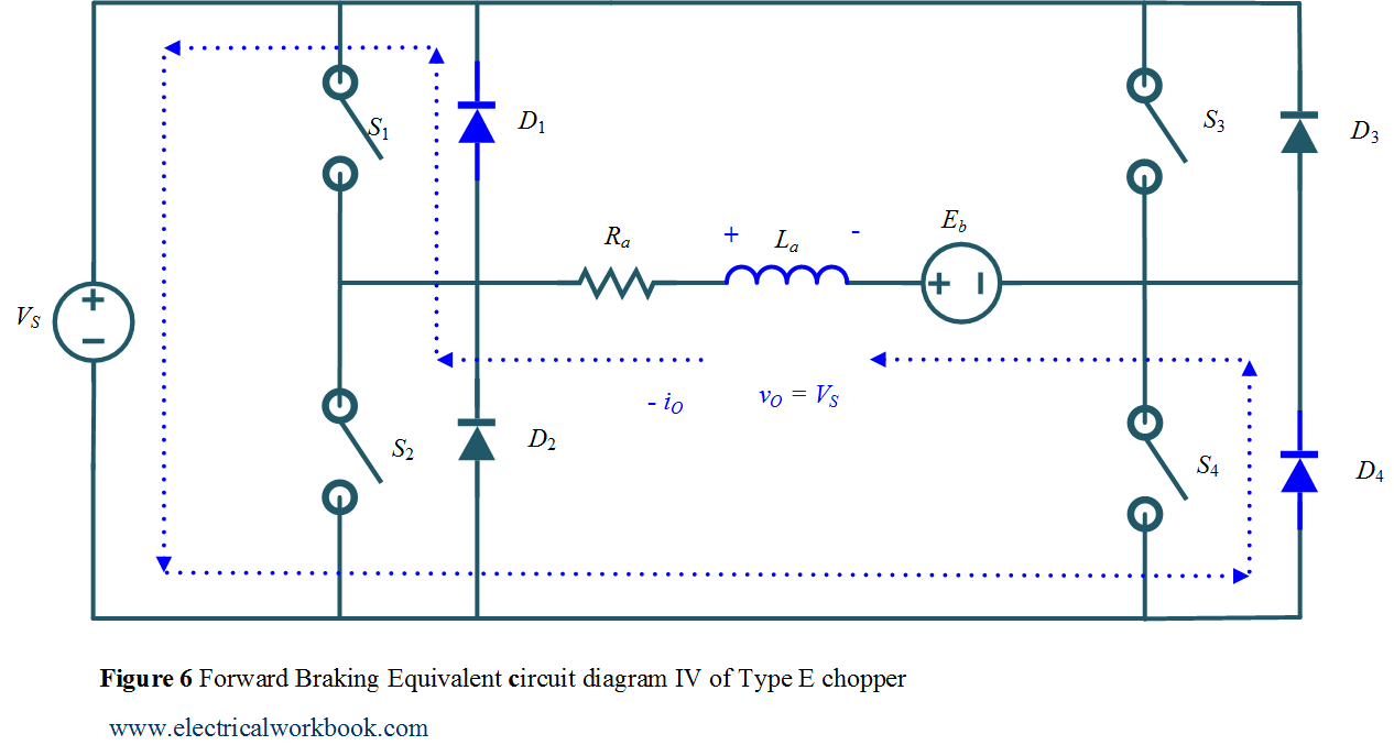
Quadrant II operation when Switch S2 turned off
The Type E chopper equivalent circuit diagram for Quadrant II is shown in Figure 6. Switch S2 turned off, diode D1 and diode D4 conducts, output voltage vO becomes positive and the output current iO is negative, inductor release energy using diodes D1 and D4, power flows from load to source and hence called as reverse braking.
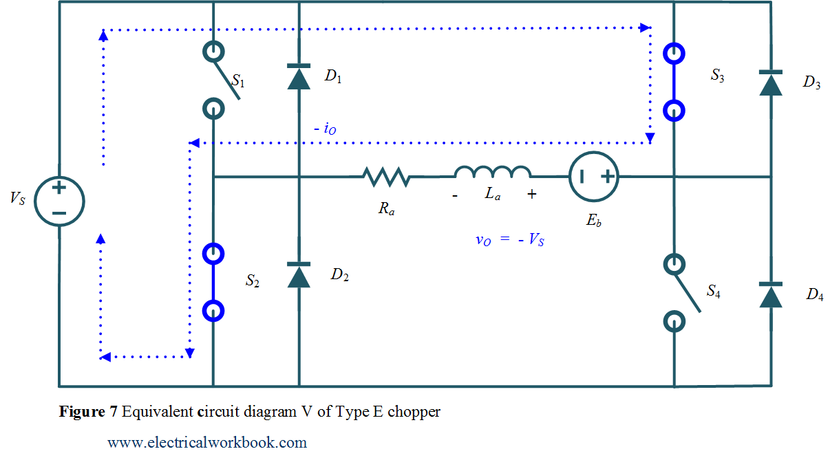
Quadrant III operation when Switch S3 turned on
The Type E chopper equivalent circuit diagram for Quadrant III is shown in Figure 7. The polarity of back emf Eb must be reversed. Here switch S3 operated, Switches S3 and S2 conducts, output voltage vO and the output current iO both are negatives, power flows from source to load and inductor stores energy, the motor rotates in the reverse direction hence called as reverse motoring.
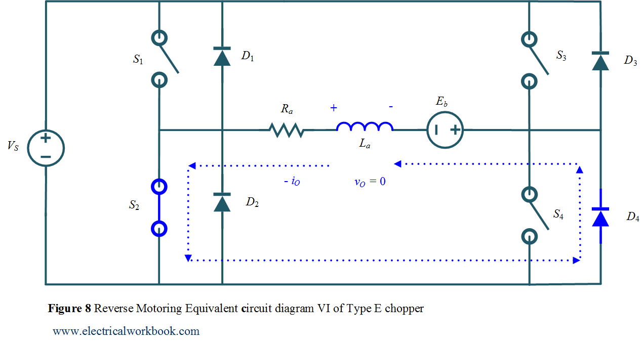
Quadrant III operation when Switch S3 turned off
The Type E chopper equivalent circuit diagram for Quadrant III is shown in Figure 8. The polarity of back emf Eb must be reversed. Switch S3 turned off but switch S2 and diode D4 conducts, output current iO is negative and the output voltage vO becomes zero, inductor release energy and freewheeling action using diode D4 takes place, the motor rotates in the reverse direction hence called as Reverse motoring.
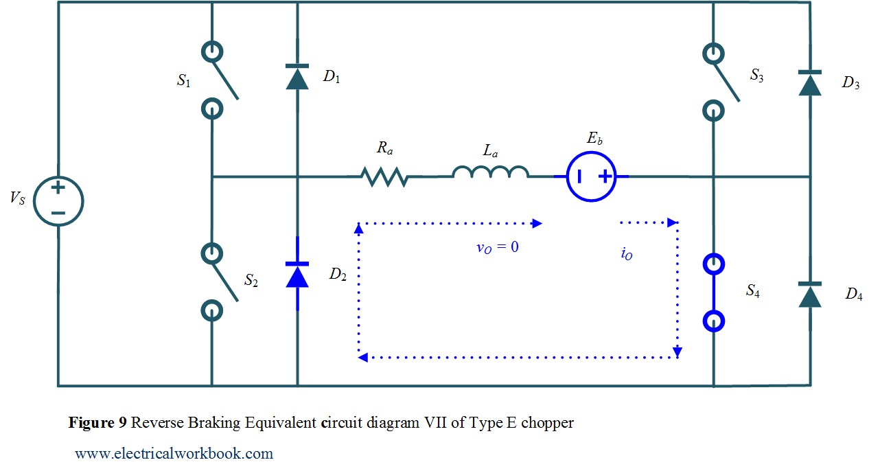
Quadrant IV operation when Switch S4 turned on
The Type E chopper equivalent circuit diagram for Quadrant IV is shown in Figure 9. The polarity of back emf Eb must be reversed. Let us assume that the motor is running in the reverse direction. Here switch S4 operated, Switches S4 and diode D2 conducts, output voltage vO is zero and Eb is responsible for the positive output current iO, machine behave as generator and inductor stores energy.
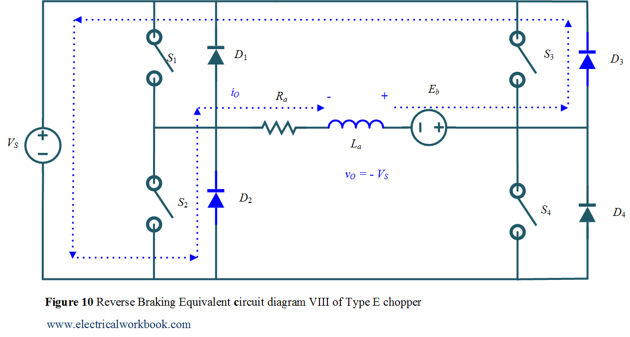
Quadrant IV operation when Switch S4 turned off
The Type E chopper equivalent circuit diagram for Quadrant IV is shown in Figure 10. The polarity of back emf Eb must be reversed. Switch S4 turned off, diode D2 and diode D3 conducts, output voltage vO becomes negative and output current iO is positive, inductor release energy using diodes D2 and D3, power flows from load to source and hence called as reverse braking.