In this topic, you study Second Quadrant Chopper or Type B Chopper or Class B Chopper v-i plane, working principle, quadrant operation, Applications, waveforms, and Circuit diagrams.
Type B chopper is basically equivalent to Step-Up Chopper.
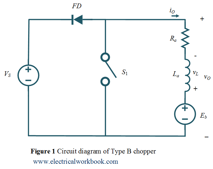
Circuit Diagram
The Type B chopper circuit diagram as shown in Figure 1. Here the motor load is assumed, Ra and La armature resistance and inductance of the motor respectively. Eb is the back emf of the motor.
vO – iO plane
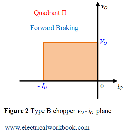
The Type B chopper operates in the Second quadrant of vO – iO plane as shown in Figure 2. Here vO is the output voltage, VO is the average output voltage, iO is the output current and IO is the average output current of Type B chopper circuit.
Quadrant II operation when Switch S1 turned on
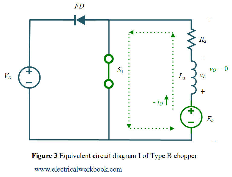
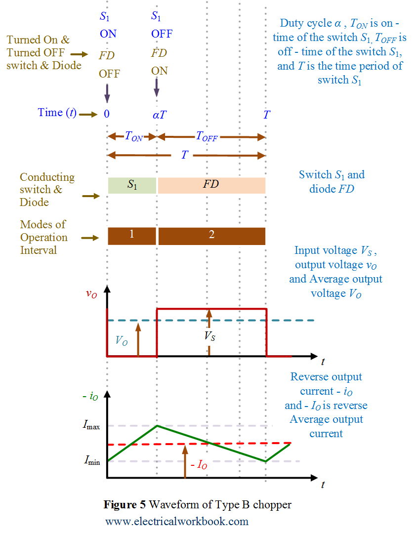
The Type B chopper circuit diagram for Quadrant II is shown in Figure 3 and the associated waveforms are shown below in Figure 5. Let us assume that the motor is running in the forward direction. When switch S1 operated, Switch S1 turned on and conducts, output voltage vO is zero and Eb is responsible for the negative output current iO, the machine behaves as generator and inductor stores energy.
Quadrant II operation when Switch S1 turned off
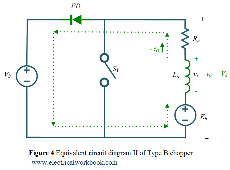
The Type E chopper equivalent circuit diagram for Quadrant II is shown in Figure 4 and the associated waveforms are below shown in Figure 5. Switch S1 turned off, diode FD conducts, output voltage vO becomes positive and the output current iO is negative, inductor release energy using diode FD, power flows from load to source and hence called as reverse braking.
Waveforms
Type B chopper associated waveforms are shown in Figure 5.
Application
This chopper is suitable for regenerative breaking application only.
Mathematical Analysis
Using the waveform as shown in Figure 1, The average output voltage write as
\[{V_O} = {V_S}\left( {\frac{{{T_{OFF}}}}{T}} \right)….(1)\]
Also
\[\frac{{{T_{OFF}}}}{T} = 1 – \alpha ….(2)\]
Put Equation 2 in Equation 1 gives
\[{V_O} = {V_S}(1 – \alpha )….(3)\]
Equation 3 describe the realtion between input dc source voltage and average output voltage for Type B chopper.