In this topic, you study Ideal Transformer.
An ideal transformer possesses following properties:
- The permeability of the core is so high that only a negligible current is required to establish the flux in it.
- There is no magnetic leakage. In other words, all the flux is confined to the iron core only and links both the windings.
- Its windings have no ohmic resistance.
- It has no losses.
In practice, it is not possible to have such an ideal transformer. However, the concept of an ideal transformer is very useful in developing step by step, the theory of the practical transformer. Therefore, to start with, let us consider such an ideal transformer and study its behaviour on no load and on load.
Ideal Transformer On No Load
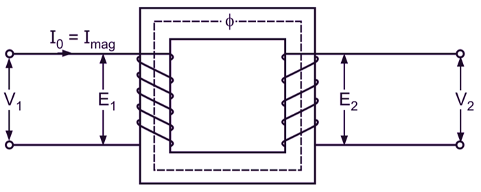
Let the transformer shown in Fig. 1 (a) be an ideal transformer. When its primary winding is connected to an alternating voltage V1, with the secondary winding open circuited, it draws a negligibly small amount of magnetizing current Imag (if the transformer is truly ideal, this magnetizing current would be zero). This current which is a purely reactive current (the primary windings being purely inductive) lags the voltage V1 by 90o and is responsible for establishing a flux Φ in the core in time phase with it. The flux produced is in time phase with the magnetizing current because it is obvious that if there were no magnetizing current, there would be no flux. This flux induces an emf E1 of self-induction in the primary winding to counterbalance the applied voltage V1 and an emf E2 in the secondary winding by mutual induction. The magnitudes of E1 and E2 are proportional to the number of turns on the primary and secondary windings. These emfs lag the flux by 90o.
(a)
(b)
Fig. 1: Ideal transformer on no load
Since the secondary circuit is open and hence the secondary terminal voltage,
V2 = E2
Also, there being a negligible voltage drop in the primary winding, the primary applied voltage V1 is equal and opposite in phase to the emf E1 induced in the primary winding. Thus, the primary applied voltage,
V1 = – E1
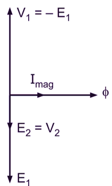
Fig. 1 (b) shows the necessary phasor diagram for the ideal transformer under consideration when on no load. The flux being common to the two windings, it is considered as a reference phasor while drawing this phasor diagram.
Ideal Transformer On Load
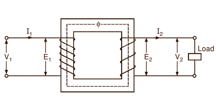
Now, if a load having a finite impedance is connected across the secondary terminals of an ideal transformer (Fig. 2 a), the current I2 flows in the secondary winding. If we consider a general case of an inductive load having a lagging power factor cos Φ2, then obviously the current I2 lags V2 by an angle Φ2 (Fig. 2 b). By Lenz’s law, this secondary current I2 produces a demagnetizing effect. Consequently, the flux and the emf induced in the primary are reduced slightly. The increased difference between the applied voltage and the emf induced in the primary causes additional current I’2 called load component to flow in the primary winding.
(a)
(b)
Fig. 2: Ideal transformer on load
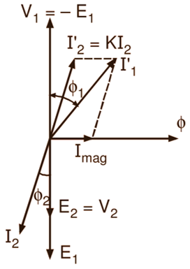
The magnitude of this current is such that the demagnetizing m.m.f. N2I2 of the secondary is nearly neutralized by the increased primary m.m.f. N2I’2 and thereby the core flux Φ is maintained at a constant value. Obviously under such condition,
\[\text{I}_{2}^{‘}={{\text{I}}_{2}}\times \frac{{{\text{N}}_{\text{2}}}}{{{\text{N}}_{\text{1}}}}=\text{K}{{\text{I}}_{\text{2}}}\]
and is in anti-phase with I2. This sequence of ructions that follow the application of the load, enables the primary to draw more power from the line to meet the increased demand of the secondary. Thus, when the transformer is on load, the total current I1 in the primary is the phasor sum of I’2 and the no-load current Imag as illustrated in the phasor diagram of Fig. 2 (b). Here, Φ1 is the phase difference V1 between and I1. Hence the power factor on the primary side is cos Φ1.