In this topic, you study Auto transformer – Theory, Diagram, Advantages & Applications.
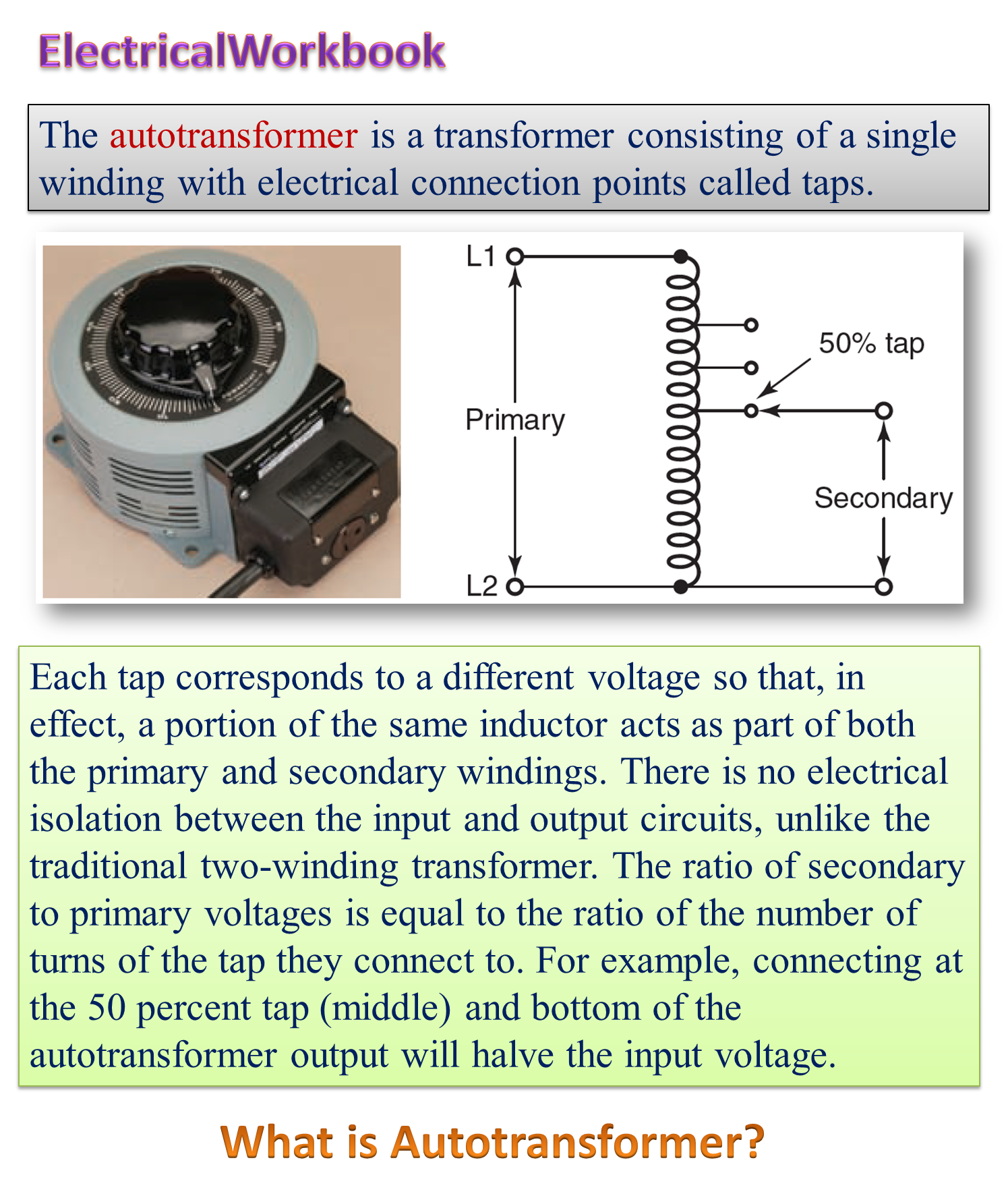
An auto transformer is a transformer having only one winding wound on a laminated magnetic core, the part of this winding being common to both the primary and secondary circuits. As an ordinary two winding transformer, it can be used as a step-down or a step-up transformer as illustrated in Figs. 1 (a) and (b) respectively.
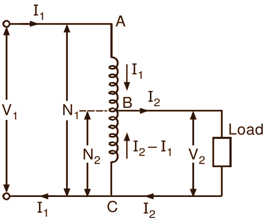
(a)
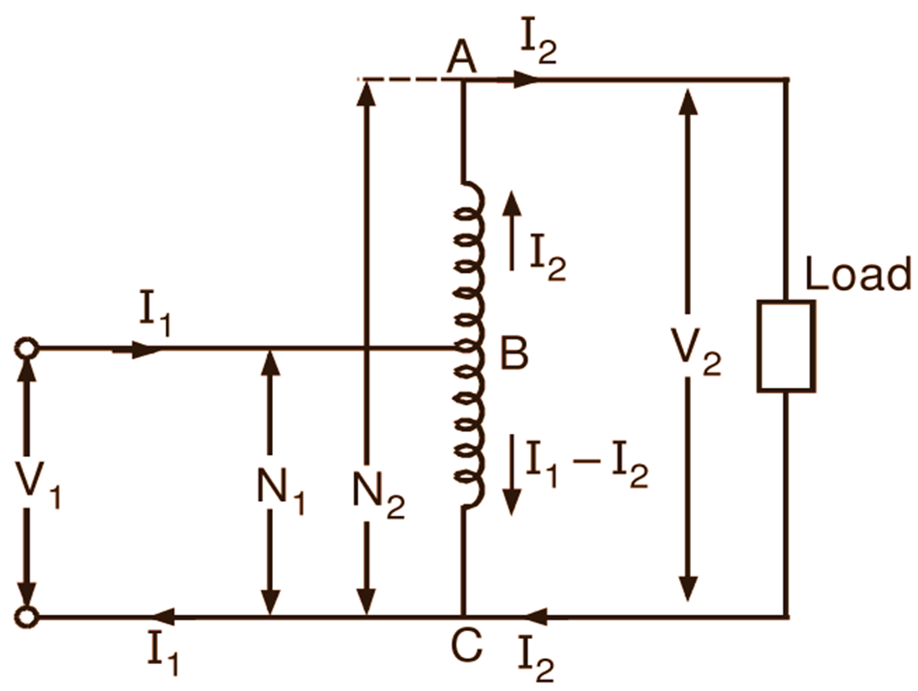
(b)
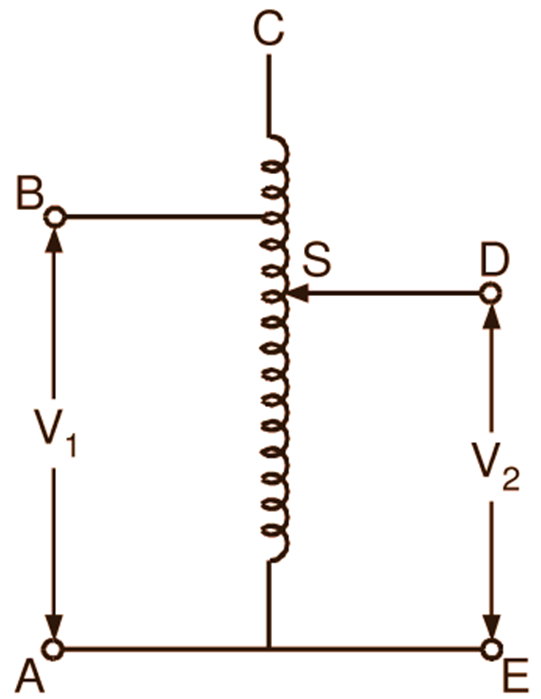
Fig. 1: (a) Step-down auto transformer, (b) Step-up auto transformer
In Fig. 1 (a), the winding AC forms the primary and its portion BC forms the secondary On the other hand, in Fig. 1 (b), the winding AC forms the secondary and its portion BC forms the primary. The performance of the auto transformer is governed by the same fundamental considerations which we have already discussed for the two winding transformers. Hence, in the case of an auto transformer also, neglecting the losses, the leakage reactance and the magnetizing current, we have
\[\frac{{{\text{V}}_{\text{2}}}}{{{\text{V}}_{\text{1}}}}=\frac{{{\text{I}}_{\text{1}}}}{{{\text{I}}_{\text{2}}}}=\frac{{{\text{N}}_{\text{2}}}}{{{\text{N}}_{\text{1}}}}=\text{K}\]
…(With usual notations)
Saving of Copper
For the same capacity (i.e. output) and voltage ratio, the auto transformer requires less copper than a conventional two winding transformer. This can be easily verified as follows. For any winding,
Cross-section of conductor ∝ Current carried, I
Total length of conductor ∝ Number of turns, N
Hence,
Volume of copper or the weight of copper ∝ NI
Now, let us use this relationship to compare the requirement of copper in the case of an ordinary two winding transformer and the auto transformer performing the same duty and having the same capacity and voltage ratio.
Two winding Transformer
Weight of copper for primary winding ∝ N1I1
Weight of copper for secondary winding ∝ N2I2
∴ Total weight of copper ∝ (N1I1 + N2I2) … (1)
Step-down Auto transformer
Current distribution in the winding is shown in Fig. 1 (a). Section AB having (N1 – N2) turns carries a current I1. Since the currents, I1 and I2 are practically in phase opposition and I2 is greater than I1, the section BC having N2 turns carries the resultant current (I2 – I1). Hence,
Weight of copper for section AB ∝ (N1 – N2) I1
Weight of copper for section BC ∝ N2 (I2 – I1)
Total weight of copper ∝ (N1 – N2) I1 + N2 (I2 – I1) …..(2)
Therefore from the equations (1) and (2), we have
\[\frac{\text{Weight of copper in step-down auto-transformer}}{\text{Weight of copper in two-winding transformer}}\]
\[=\frac{({{\text{N}}_{1}}-{{\text{N}}_{2}}){{\text{I}}_{1}}+{{\text{N}}_{2}}({{\text{I}}_{2}}-{{\text{I}}_{1}})}{{{\text{N}}_{1}}{{\text{I}}_{1}}+{{\text{N}}_{2}}{{\text{I}}_{2}}}\]
\[=\frac{{{\text{N}}_{1}}{{\text{I}}_{1}}+{{\text{N}}_{2}}{{\text{I}}_{2}}-2{{\text{N}}_{2}}{{\text{I}}_{1}}}{{{\text{N}}_{1}}{{\text{I}}_{1}}+{{\text{N}}_{2}}{{\text{I}}_{2}}}\]
\[=1-\frac{2{{\text{N}}_{\text{2}}}{{\text{I}}_{1}}}{{{\text{N}}_{1}}{{\text{I}}_{1}}+{{\text{N}}_{2}}{{\text{I}}_{2}}}\]
\[=1-\frac{2}{\left( {{\text{N}}_{1}}/{{\text{N}}_{2}} \right)+\left( {{\text{I}}_{2}}/{{\text{I}}_{\text{1}}} \right)}\]
Since,
\[\frac{{{\text{N}}_{\text{1}}}}{{{\text{N}}_{\text{2}}}}=\frac{{{\text{I}}_{\text{2}}}}{{{\text{I}}_{\text{1}}}}=\frac{1}{\text{K}}\]
Thus,
\[=1-\text{K}\]
Hence,
Saving of copper in step-down auto-transformer
= (Weight of copper in two-winding transformer)
– (Weight of copper in step-down auto-transformer)
= (Weight of copper in two-winding transformer)
– (1 – K) (Weight of copper in two-winding transformer)
= K × (Weight of copper in two-winding transformer)
..(3)
Step-up Auto transformer
Current distribution in the winding is shown in Fig. 1 (b). Section AB having (N2 – N1) turns carries a current I2. Since the currents, I1 and I2 are practically in phase opposition I1 and I2 being greater than , the section BC having N1 turns carries the resultant current (I1 – I2). Hence,
Weight of copper for section AB ∝ (N2 – N1) I2
Weight of copper for section BC ∝ N1 (I1 – I2)
Total weight of copper ∝ (N2 – N1) I2 + N1 (I1 – I2) …..(4)
Therefore from the equations (1) and (4), we have
\[\frac{\text{Weight of copper in step-up auto-transformer}}{\text{Weight of copper in two-winding transformer}}\]
\[=\frac{({{\text{N}}_{2}}-{{\text{N}}_{1}}){{\text{I}}_{2}}+{{\text{N}}_{1}}({{\text{I}}_{1}}-{{\text{I}}_{2}})}{{{\text{N}}_{2}}{{\text{I}}_{2}}+{{\text{N}}_{1}}{{\text{I}}_{1}}}\]
\[=\frac{{{\text{N}}_{1}}{{\text{I}}_{1}}+{{\text{N}}_{2}}{{\text{I}}_{2}}-2{{\text{N}}_{1}}{{\text{I}}_{2}}}{{{\text{N}}_{1}}{{\text{I}}_{1}}+{{\text{N}}_{2}}{{\text{I}}_{2}}}\]
\[=1-\frac{2{{\text{N}}_{\text{1}}}{{\text{I}}_{2}}}{{{\text{N}}_{1}}{{\text{I}}_{1}}+{{\text{N}}_{2}}{{\text{I}}_{2}}}\]
\[=1-\frac{2}{\left( {{\text{I}}_{1}}/{{\text{I}}_{2}} \right)+\left( {{\text{N}}_{2}}/{{\text{N}}_{\text{1}}} \right)}\]
Since,
\[\frac{{{\text{I}}_{\text{1}}}}{{{\text{I}}_{\text{2}}}}=\frac{{{\text{N}}_{\text{2}}}}{{{\text{N}}_{\text{1}}}}=\text{K}\]
Thus,
\[=1-\frac{\text{1}}{\text{K}}\]
Hence,
Saving of copper in step-up auto-transformer
= (1/K) × Weight of copper in two-winding transformer …..(5)
From the equations (3) and (5), it is obvious that the nearer the ratio of the transformation is to unity, the greater is the saving of copper.
Advantages of Auto transformer
- Weight of copper required in an auto transformer is always less than that of the conventional two winding transformer and hence it is comparatively cheaper. The saving of copper is increased as the transformation ratio approaches unity.
- The resistance and leakage reactance of an auto transformer being less than the corresponding two winding transformer, its regulation is better.
- I2R losses being less, the efficiency of an auto transformer is higher than that of the two winding transformer.
Disadvantages of Auto transformer
In the case of an auto transformer, there is always a risk of serious electric shock particularly when it is used in the high voltage circuit. This is because the low voltage and high voltage sides are not electrically separate.
Applications of Auto transformer
- For stating squirrel-cage induction motors and synchronous motors.
- For interconnecting ac systems having roughly the same operating voltage.
- As boosters to raise the voltage in ac feeders.
- As furnace transformers for getting suitable supply voltage.
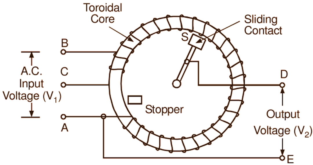
- As variacs for getting continuously variable ac supply voltage. This is the most common application of the auto transformers. We know that ordinary rheostat can be used as a potential divider for getting continuously variable ac voltage. But it is useful only for stepping down the voltage. On the other hand, the auto transformer even though costlier has the distinct advantage that it can step-up as well as step-down the voltage and has negligible losses. Fig. 2 (a) shows the constructional details of a single phase variac and Fig. 2 (b) the necessary connection diagram.
(a)
(b)
Fig. 2: Single phase variac
It has its winding wound on a toroidal core. Input voltage (V1) is applied between the terminals A and B. A continuously variable output voltage (V2) from zero to about 120