An inclined tube manometer is a cistern or well type manometer having an inclined column. It is also known as ‘draft gauge’. The schematic of an inclined tube manometer is shown in figure 1.
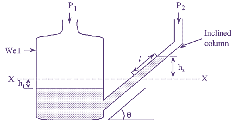
Figure 1: Inclined Tube Manometer.
Working & Construction of Inclined Tube Manometer
In an inclined tube manometer, the limb having a large cross-sectional area is known as well and the limb having small cross-sectional area is known as column. Therefore, it is considered as a single-column manometer. The column of this manometer is inclined at an angle θ with respect to the horizontal. The tube is filled with the manometer liquid.
Derivation & Formula of Inclined Tube Manometer
When no pressures are applied or when equal pressures are applied to the limbs of the manometer, the liquid in both the limbs (well and column) will be at same level (i.e. 0-0 level). When two different pressures are applied to the limbs, the liquid level decreases in the well, while the liquid level increases in the inclined column.
This leads to a difference between the liquid levels of the two limbs. The difference in the liquid levels is given as,
\[\Delta h\text{ }=\text{ }{{h}_{1}}+\text{ }{{h}_{2}}\]
Where,
h1 = Level of liquid from 0-0 level in well
h2 = Level of liquid from 0-0 level in column
Δh corresponds to the difference of the two pressures applied to the manometer and the relationship between Δh and pressures is given by tile following equation.
\[\Delta h=\frac{{{P}_{1}}-{{P}_{2}}}{\rho g}\]
also
\[{{h}_{1}}+{{h}_{2}}=\frac{{{P}_{1}}-{{P}_{2}}}{\rho g}\]
Where.
P1 = Pressure applied to well
P2 = Pressure applied to column
Due to increase and decrease in liquid level of column and well respectively, the displacement in the volume of the two limbs is equal.
i.e.
\[{{V}_{1}}={{V}_{2}}\]
\[{{A}_{1}}{{V}_{1}}={{A}_{2}}{{V}_{2}}\]
\[{{h}_{1}}=\frac{{{A}_{2}}}{{{A}_{1}}}{{h}_{2}}\]
But,
\[{{h}_{2}}=l.\sin \theta ….(1)\]
Where,
l = Slant height of the liquid in inclined column
A1 = Cross-sectional area of well
A2 = Cross-sectional area of column
From equation (1), we have.
\[\left( {{P}_{1}}-{{P}_{2}} \right)=\rho g\left( {{h}_{1}}+{{h}_{2}} \right)\]
\[=\rho g\left( \frac{{{A}_{2}}}{{{A}_{1}}}{{h}_{2}}+{{h}_{2}} \right)\]
\[=\rho g{{h}_{2}}\left( \frac{{{A}_{2}}}{{{A}_{1}}}+1 \right)\]
Also
\[\left( {{P}_{1}}-{{P}_{2}} \right)=\rho gl.\sin \theta \left( \frac{{{A}_{2}}}{{{A}_{1}}}+1 \right)\]
If
\[{{A}_{1}}\gg {{A}_{2}}\]
\[\frac{{{A}_{2}}}{{{A}_{1}}}\approx 0\]
\[\left( {{P}_{1}}-{{P}_{2}} \right)=\rho gl.\sin \theta ..(2)\]
\[\left( {{P}_{1}}-{{P}_{2}} \right)=\rho g{{h}_{2}}….(3)\]
Equations (2) and (3) represents the equations for differential pressure based on the movement of the liquid in the inclined only i.e., the differential pressure can be determined by measuring either h2 or l.