In this topic, you study Inductors in Series.
When two or more inductive coils having no mutual inductance between them are connected in series, their total inductance can be found in the same manner as the total resistance of resistors in series. For example, in a situation where there are n series-connected coils in an electric circuit (Fig. 1), their total inductance (LT) is equal to the sum of their individual self-inductances i.e.
\[{{\text{L}}_{\text{T}}}=\text{ }{{\text{L}}_{1}}+\text{ }{{\text{L}}_{2}}+\text{ }{{\text{L}}_{3}}+\text{ }….+\text{ }{{\text{L}}_{\text{n}}}\]
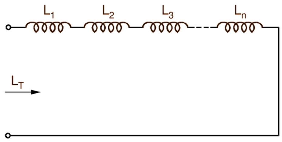
Fig. 1: Inductors in Series
Inductors in Parallel
Also, if such n coils having no mutual inductance between them are connected in parallel (Fig. 2), their total inductance can be found in the same manner as the total resistance of resistors in parallel i.e.
\[\frac{1}{{{\text{L}}_{\text{T}}}}=\text{ }\frac{1}{{{\text{L}}_{1}}}+\text{ }\frac{1}{{{\text{L}}_{2}}}+\text{ }\frac{1}{{{\text{L}}_{3}}}+\text{ }……..+\text{ }\frac{1}{{{\text{L}}_{\text{n}}}}\]
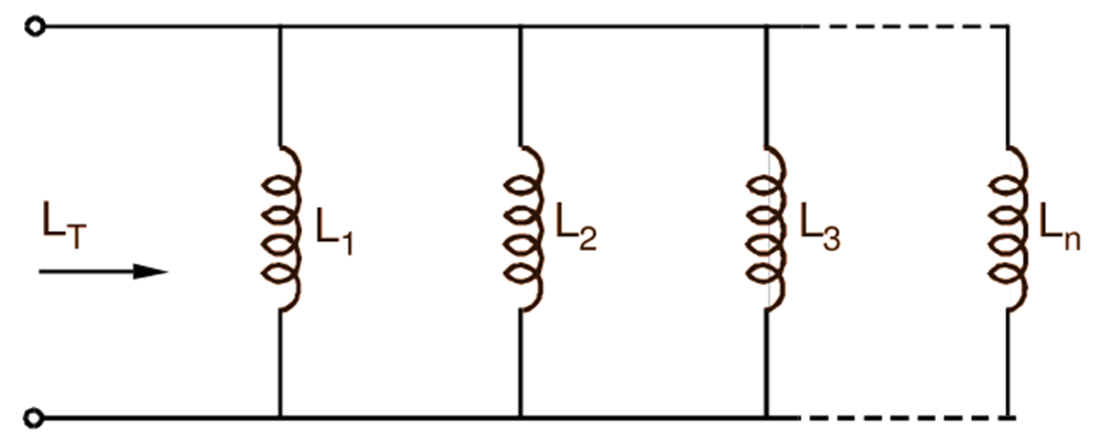
Fig. 2: Inductors in Series
INDUCTANCE OF INDUCTIVELY COUPLED COILS IN SERIES
If the two coils are connected in series so that their fluxes, at any instant, are in the same direction as shown in Fig. 3 (a), they are said to be cumulatively coupled and such series connection is known as series aiding. On the other hand, if their fluxes are in the opposite directions Fig. 3 (b), the coils are said to be differentially coupled and the series connection under such condition is known as series opposing. Let self-inductances of the inductively coupled coils A and C in Fig. 3 be L1 and L2 respectively and let M be their mutual inductance. If these coils are connected in series aiding (Fig. 3 a), then the total emf (e) induced in the circuit due to a current changing at the rate di/dt is the sum of self induced emfs and mutually induced emfs in the coils, i.e.
\[\text{e}=-{{\text{L}}_{1}}\frac{\text{di}}{\text{dt}}-\text{ }{{\text{L}}_{2}}\frac{\text{di}}{\text{dt}}-\text{ M}\frac{\text{di}}{\text{dt}}-\text{M}\frac{\text{di}}{\text{dt}}\]
….(1)
\[\text{e}=-\text{ }({{\text{L}}_{1}}+\text{ }{{\text{L}}_{2}}+\text{ 2M)}\frac{\text{di}}{\text{dt}}\]
….(2)
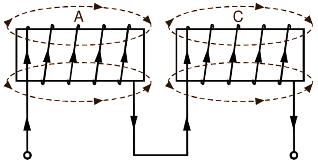
(a)
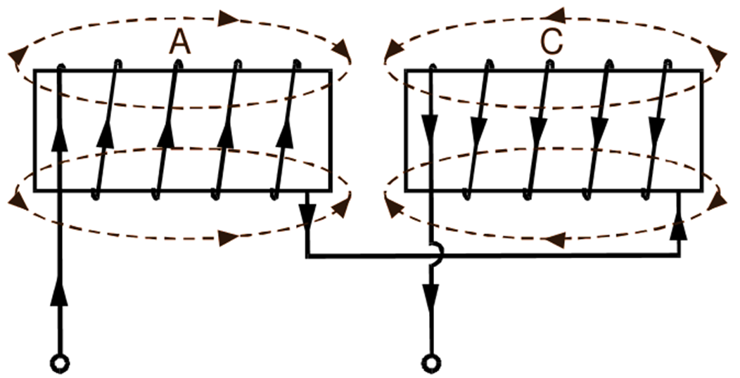
(b)
Fig. 1: Inductively coupled coils connected in series (a) Series aiding, (b) Series opposing
Here, all the e.m.f.s have negative sign because they oppose the applied e.m.f. Now, if L is the equivalent inductance of the circuit, then obviously,
\[\text{e}=-\text{ L}\frac{\text{di}}{\text{dt}}\]
Equating the equations (1) and (2), we have
\[\text{L}={{\text{L}}_{1}}+\text{ }{{\text{L}}_{2}}+\text{ 2M}\]
- If the two coils are connected in series opposing (Fig. 3 b), then the polarity of the mutually induced e.m.f.s is reversed. Hence,
\[\text{e}=-{{\text{L}}_{1}}\frac{\text{di}}{\text{dt}}-\text{ }{{\text{L}}_{2}}\frac{\text{di}}{\text{dt}}+\text{ M}\frac{\text{di}}{\text{dt}}+\text{M}\frac{\text{di}}{\text{dt}}\]
\[\text{e}=-\text{ }({{\text{L}}_{1}}+\text{ }{{\text{L}}_{2}}-\text{ 2M)}\frac{\text{di}}{\text{dt}}\]
Also.
\[\text{e}=-\text{ L}\frac{\text{di}}{\text{dt}}\]
where L is the equivalent inductance of the circuit under such condition.
\[\text{L}={{\text{L}}_{1}}+\text{ }{{\text{L}}_{2}}-\text{ 2M}\]