In this topic, you study Rotor resistance starter – Working & Diagram.
This type of starter essentially consists of a three phase star connected controlling resistance. The starter unit also includes a line switching contactor for the Stator along with usual no-voltage (or low-voltage) and over-current protective devices.
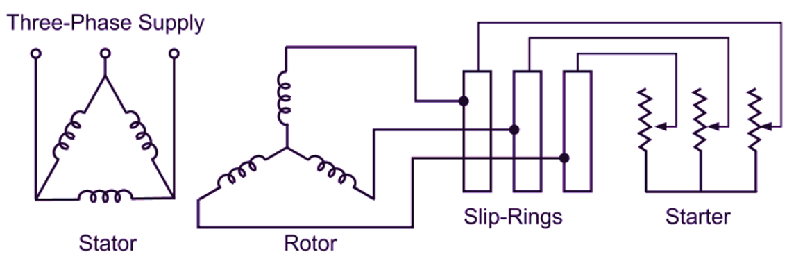
Fig. 1: Rotor resistance starter
For starting the motor, the controlling resistance is inserted in the rotor circuit through the slip-rings and brushes and full supply voltage is applied across the Stator terminals as illustrated in Fig. 1. The starting resistance introduced in the rotor circuit is gradually cut out as the motor speeds up. This resistance cutting may be automatic or manual. In large motors, when the resistance is completely cut out from the rotor circuit, the slip-rings are short circuited with the help of a metallic collar and at the same time the brushes are lifted automatically from them. This avoids power loss due to brush friction and the lead resistance. A mechanical interlocking is also normally provided to prevent the starting of the motor without the resistance in the rotor circuit.