Sine bar is used for measurement of angle of given job or for setting an angle, sine bar is one of the famous instrument for angle measurement. It can be used in combination of slip gauge set and dial gauge for measurement of angle.
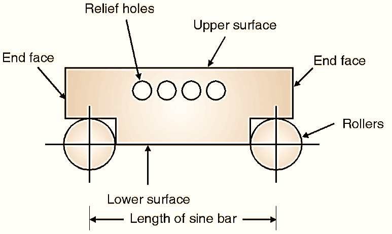
Figure 1: Sine bar.
A sine bar is a precision measuring instrument usedto measure or set angles accurately. It operates based on the principles of trigonometry, specifically the sine function. It is as shown in Fig. 1, which consists of two rollers of same diameters fixed at a distance (L) between them, called as length of sine bar.
Working Principle of Sine Bar
The sine bar works on the principle of trigonometry. It is primarily used to measure or set angles. The angle of inclination (θ) is calculated using the formula:
\[ \sin \theta = \frac{\text{Height of gauge block (h)}}{\text{Length of sine bar (L)}}\]
To measure an angle:
- One roller is placed on a flat surface, while the other is raised using gauge blocks.
- The height of the gauge blocks corresponds to the sine of the angle to be measured.
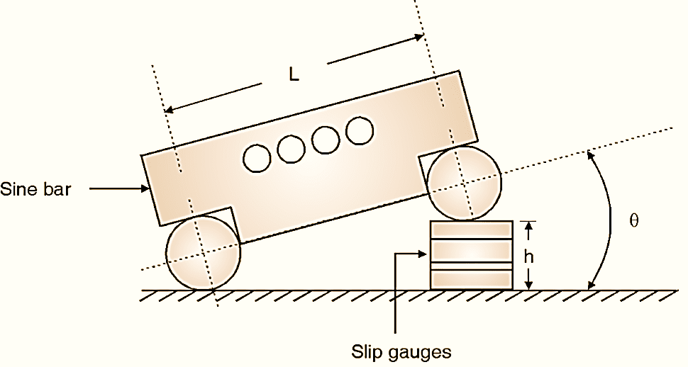
Figure 2: Principle of Sine bar.
Sine bar works on basic principle of trigonometric sine function as explained in Figure 2. If one of the roller is lifted and the appropriate value of slip gauge are placed (total height, h), then,
\[ \sin \theta =\frac{h}{L}\]
\[ \theta ={{\sin }^{-1}}(h/L)\]
To calculate θ, sine function is used in above Equation, hence the instrument is called as sine bar.
Construction of Sine Bar
A sine bar consists of:
- Body: A precisely machined rectangular block.
- Rollers: Two accurately machined cylindrical rollers fixed at the ends of the bar. The distance between the roller centers is standardized (e.g., 100 mm or 200 mm).
- Relief Holes: These reduce the weight and ensure easy handling.
- Upper Surface: Precisely flat and used as a reference for placing the workpiece.
- Lower Surface: Parallel to the upper surface, forming the base.
- End Faces: Flat and perpendicular to the length of the sine bar.
Types of Sine Bars
- Plain Sine Bar: Standard sine bar used for general angular measurements.
- Compound Sine Bar: Used for measuring compound angles.
- Sine Center: Designed to hold cylindrical workpieces.
- Sine Table: A sine bar integrated into a table for easier adjustment.
- Special Sine Bars: Custom-designed for specific applications.
Advantages of Sine Bar
- Highly accurate for angle measurements.
- Simple to use and reliable.
- Requires minimal maintenance.
- Suitable for precise machining and inspection tasks.
Limitations of Sine Bar
- Used for angle measurement below 45º only.
- Time consuming process of measurement.
- Accuracy/grade of sine bar matters on accuracy of angle measured.
Errors in Sine Bar
Following could be errors in sine bar, by removing which accuracy can be improved.
- Roller diameters
- True roller cylinders
- Error in center distance of rollers
- Setting of rollers
- Flatness of upper face of sine bar
Care of Sine Bar
- Proper length of sine bar is to be selected.
- Sine bar should be free from dust, dirt etc.
- Clamping of job should be done properly on sine bar while measuring.
Uses of Sine Bar
- Setting workpieces at specific angles in machining operations.
- Checking angles of machine parts and tools.
- Calibrating and inspecting angular gauges.
- Measuring taper angles of components.
Use for Small Job Measurement / Taper Plug Gauge :
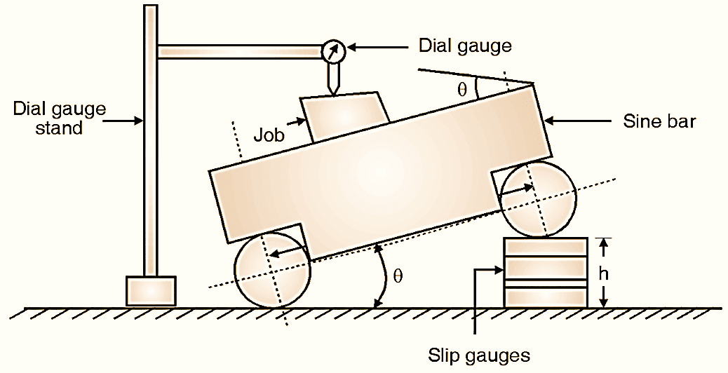
Figure 3: Small job measurement using Sine bar.
First, calculate the approximate value of angle of given job using bevel protractor. (e.g. 5º). Calculate the height h for the same angle using,
\[\sin \theta =h/L\]
\[\sin 5=h/100\text{ }\left( \text{Assuming L = 100 mm} \right)\]
\[h=8.7155\text{ mm}\]
Arrange slip gauges of size 8.715 mm by selecting from a slip gauge box by using proper wringing method (e.g. 8.715 = 1.005 + 1.41 + 1.3 + 5). Put the assembled slip gauges under one roller of sine bar (Fig. 3) and set the dial gauge with stand. By moving the dial gauge throughout the length of job, observe the deviation of dial gauge pointer. Rearrange the slip sizes by adding or subtracting slips if required and repeat till zero deviation is observed. For example, at height of 8.710 mm, zero deviation is observed. Calculate, new angle θ using the same Equation.
\[\sin \theta =\frac{h}{L}=\frac{8.710}{100}\]
\[\theta =4{}^\circ 5{9}’48.4{6}”\]
Use for Big Job Measurement :
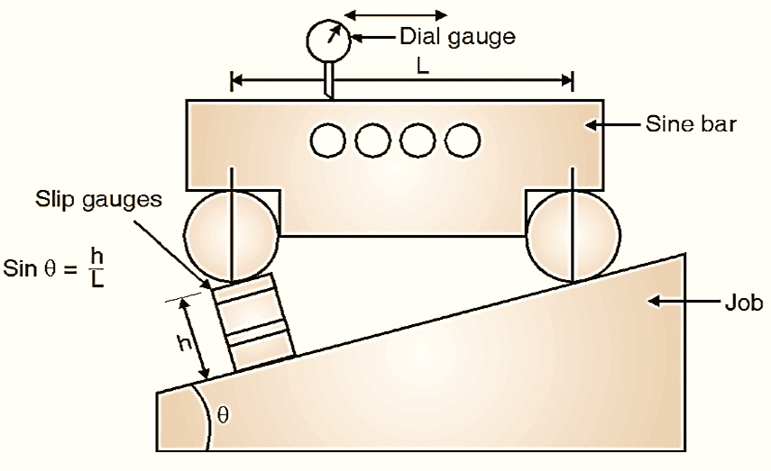
Figure 4: Big job measurement using Sine bar.
Sine bar can also be used for measurement of angles of heavy jobs. Basic principle is same, but the arrangement is only different i.e. sine bar is to be kept on the job. (Fig. 4). Place proper height of slip gauges by making arrangement as shown in Fig. 4 and get θ.
Why is Sine Bar Limited Below 45°?
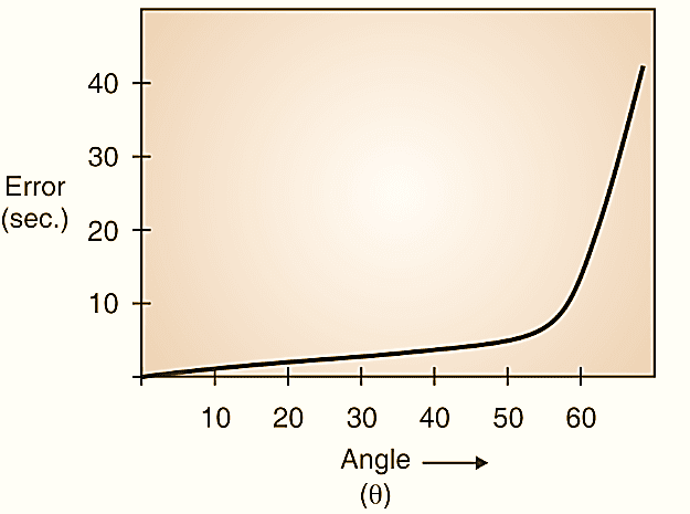
Figure 5.
We know that sinθ = h/l is the basic principle of working of sine bar. Differentiating equation,
\[\cos \theta .d\theta =\frac{l.dh-h.dl}{{{l}^{2}}}=\frac{dh}{l}-\frac{h.dl}{{{l}^{2}}}\]
\[\cos \theta .d\theta =\frac{dh}{l}\sin \theta -\frac{dl}{l}\sin \theta \]
\[d\theta =\tan \theta \left( \frac{dh}{h}-\frac{dl}{l} \right)\]
This indicates that error is a function of tan θ and below 45º error is smaller which suddenly increases above 45º. Because of this sine bar is preferred for measuring angle below 45º. Refer Fig. 5.