Single phase half wave controlled rectifier consists of single thyristor feeding DC power to the resistive load, resistive-inductive load, and resistive-inductive load with a free-wheeling diode.
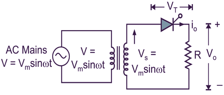
Fig. 1: Single Phase Half Wave Controlled Rectifier Circuit Diagram.
Fig. 1 (a) shows the simple circuit of Single phase half wave controlled rectifier with resistive load. The supply voltage is AC (VS = Vm sin ωt) as shown in Fig. 1 (a). If positive gate voltage is applied to gate-cathode junction and anode voltage is positive then only SCR conducts.
Single Phase Half Wave Controlled Rectifier Working:
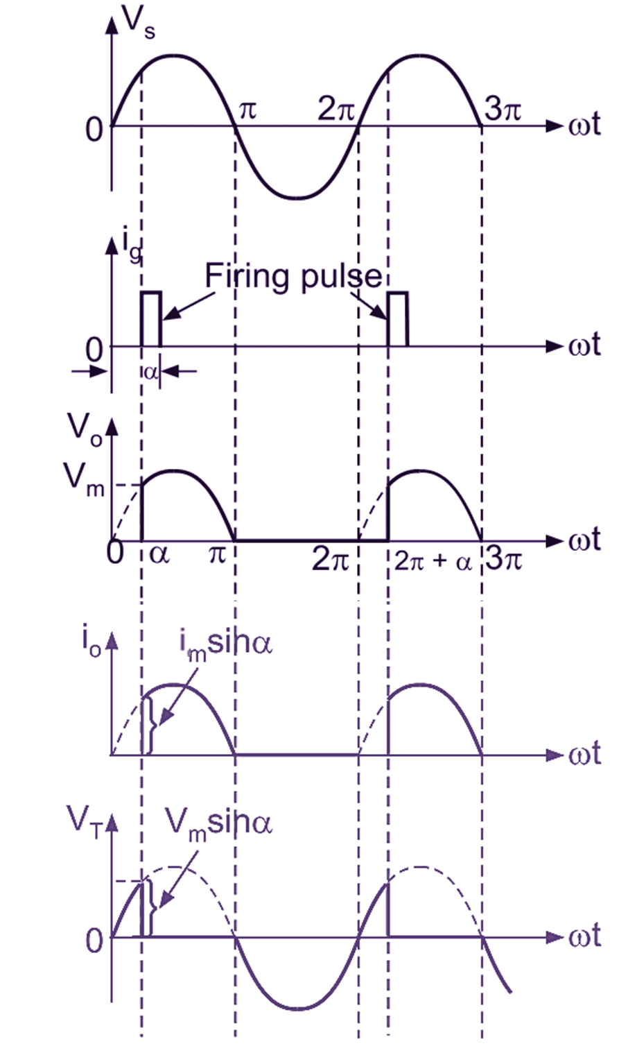
Fig. 2: Single Phase Half Wave Controlled Rectifier Waveforms.
The operation of this converter is in two modes.
Mode 1 :(α to π):
During positive half cycle of AC in put voltage (see Figure 2), the thyristor anode is more positive with respect to cathode and thyristor conducts (said to be forward biased). Thyristor fired (conduct) at ωt = α (α is called as delay angle or firing angle), the load is directly connected to supply i.e. Vo = VS. Thyristor conducts upto ωt = π and commutation takes place at ωt = π. The average value of output voltage and current is positive. The converter operates in the first quadrant of V0 – i0 characteristics.
Mode 2: (π to π + α):
During negative half-cycle of AC input voltage, the cathode of thyristor is more positive with respect to anode, the thyristor is said to be reverse biased condition (OFF state). Therefore the average average value of output voltage Vo = 0.
For resistive load, the current io is in phase with Vo as shown in Fig. 2. Firing angle of a thyristor is measured from the instant at which SCR starts conducting. If thyristor is replaced by diode, it would begin conduction at ωt = 0, 2π, 4 π etc., firing angle is measured from this instant. “A Firing Angle is defined as the Instant at which SCR Conducts”.
Fig. 2 shows the output and input current waveforms, where the thyristor conducts from ωt = α to π, (2π + α) to 3 π and so on. Over the firing angle delay α, load voltage V0 = 0 but during conduction angle (π – α), Vo = VS. As firing angle is increased from 0 to π, the average load voltage decreases from the largest value to zero.
Formulas of Single phase half wave controlled rectifier
Average value of output voltage
\[{{\text{V}}_{\text{o}}}=\frac{{{\text{V}}_{\text{m}}}}{\text{2 }\!\!\pi\!\!\text{ }}\left[ 1+\cos \alpha \right]\]
RMS value of output voltage
\[{{\text{V}}_{\text{rms}}}=\frac{{{\text{V}}_{\text{m}}}}{\text{2}}{{\left[ \frac{\text{1}}{\text{ }\!\!\pi\!\!\text{ }}\left( \text{ }\!\!\pi\!\!\text{ }-\text{ }\!\!\alpha\!\!\text{ }+\frac{\text{sin2 }\!\!\alpha\!\!\text{ }}{\text{2}} \right) \right]}^{\text{1/2}}}\]