Energy is product of power of time. Electrical energy can be measured in watt second. But the convenient reading unit in practical world is kilo watt hours i.e. kWh, while quantifying energy it is expressed in units consumed.
1 unit of energy = 1 kWh
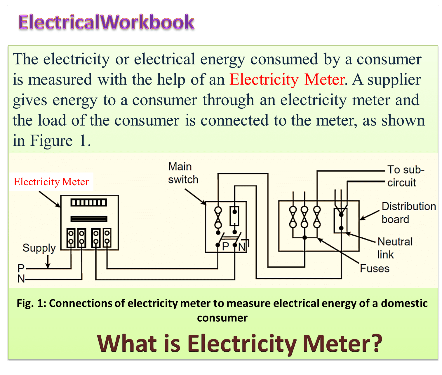
The electricity supply company supplies electrical power to consumers (utility). This power consumed by consumer over a period of time is measured i.e. energy is measured in terms of units. The rate of cost per unit is decided by the supplier. The meter which measures the electrical energy is known as Electricity Meter.
The LT (Low Tension) consumers have to use single phase electricity meters and HT (High Tension) consumers have to use three phase electricity meter. The electrical connection of electricity meter is similar to wattmeter.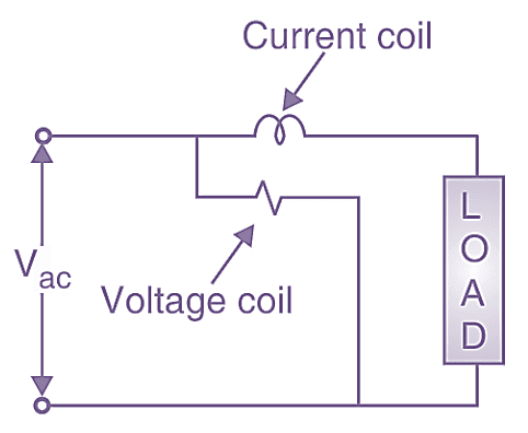
Figure 2: Elements in electricity meter.
There are two elements in electricity meter:
- Current coil or series coil
- Voltage coil or shunt coil
The current coil is in series with the load and voltage coil is in parallel to the load and supply (See Figure 2).
Working Principle of Electricity Meter
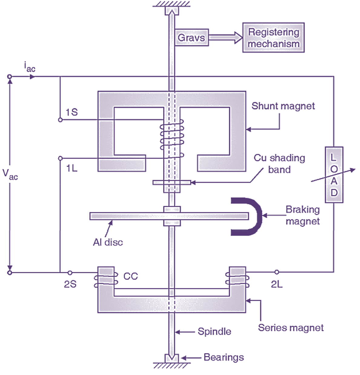
Fig. 3: Constructional details of single phase induction type electricity meter.
An alternating current is passed through the coils of two electromagnets-shunt magnet and series magnet. These two electromagnets produce their own magnetic flux. The magnetic flux of shunt magnet is proportional to supply voltage and magnetic flux of series magnet is proportional to load current. These two fluxes are alternating in nature. The interactions of two fluxes produce a resultant flux. An aluminium disc is suspended between the shunt magnet and series magnet. The resultant flux is also alternating in nature. This resultant flux links with the aluminium disc and induces eddy currents in the disc. These eddy currents interact with the resultant flux and a torque is produced on the disc. The disc thus starts rotating. The rotation of disc is proportional to power i.e. N ∝ VI cos φ. These revolutions can be measured over a period of time and thus energy can be quantified.
Construction of Electricity Meter
The entire parts of single phase induction type electricity meter can be divided into four different systems.
- Driving system
- Moving system
- Braking system
- Registering mechanism
Moving system and registering mechanism
It consists of aluminium disc suspended between shunt and series magnet as shown in Fig. 3. The aluminium disc is mounted on spindle which is supported at both ends by jewel bearings. The disc rotates and causes rotation of spindle. The spindle transfers its motion to gears connected to registering mechanism. This registering mechanism counts number of revolution over a period of time i.e. energy. The units consumed are displayed in terms of numbers.
Braking system
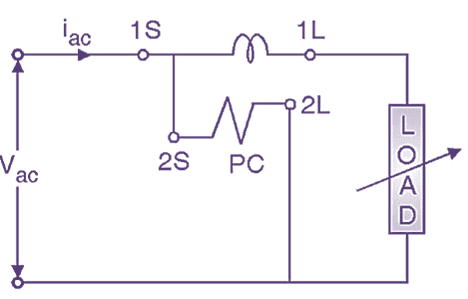
Fig. 4: Circuit diagram / Connection diagram of single phase induction type electricity meter
This system is for speed adjustment of disc. A permanent magnet known as braking magnet is provided at the edge of the disc as shown in Fig. 3. If speed of the disc is to be reduced, the braking magnet is taken towards the edge of the disc. If speed of the disc is to be increased, the braking magnet is taken towards centre of the disc. The connections of electricity meter are similar to wattmeter (see Figure 4). The current coil terminals are designated as 1S – 1L. The pressure coil terminals are designated as 2S – 2L.
Driving system
It consists of two electromagnets shunt magnet and series magnet. Shunt magnet is E-shaped and series magnet is C shaped. Shunt magnet is wound with pressure coil (PC). Shunt magnet is E-shaped and series magnet is C shaped. Shunt magnet is wound with pressure coil (PC) of thin conductor with large number of turns.
Series magnet is wound with current coil (CC) of thick conductor with few numbers of turns. The electromagnets are made up of silicon steel stampings. Copper shading bands are provided on central limb of shunt magnet. Due to this copper shading band is for lag adjustment. Hence it is also known as lag adjustment device. It brings the shunt magnet flux at 90° lagging position w.r.t. supply voltage. For satisfactory operation of electricity meter the phase angle (φ) between supply voltage V and pressure coil flux should be 90°.
V = KVI cos φ sin α = KVI cos φ sin (90°)
N = KVI cos φ
where,
V pressure coil voltage
I = load current
φ = p.f. angle
α = phase angle or angle of lag
The Cu shading bond adjusts angle α to 90°
Thus the disc revolutions are proportional to VI cos φ i.e. power. These revolutions are measured over a period of time to measure energy.