Superheterodyne receivers have been developed to overcome the shortcomings of straight radio receivers. All modern radio receivers operate on superheterodyne principle.
In superheterodyne receivers, the selected radio frequency signal is changed to a lower fixed frequency known as the intermediate frequency (IF). In order to obtain the intermediate frequency signal, an electronic circuit called mixer is incorporated in the receiver. There are two input signals given to the mixer—the amplified radio frequency modulated signal from the RF amplifier and a radio frequency sinusoidal signal produced by an oscillator called the local oscillator circuit. The local oscillator circuit is a part of the superheterodyne receiver and generates radio frequency signals with frequency higher than the incoming signal frequency by 455 kHz. The mixer circuit mixes these two signals and gives an output signal having a frequency equal to the difference in the frequencies of the incoming signal and the locally generated signal. In other words, the signal output of the mixer has a frequency of 455 kHz. Since the incoming radio frequency signal is amplitude modulated; the intermediate frequency signal is also amplitude modulated but its centre frequency is fixed and equal to 455 kHz.
In order to appreciate the importance of the mixer circuit, let us consider two incoming signals of frequencies 1000 kHz in the medium wave band and 27 MHz in the short wave II band. To receive the first signal, the local oscillator frequency is adjusted to 1455 kHz. In order to receive the second signal, the local oscillator is set to 27.45 MHz. In both the cases, the mixer output is an amplitude modulated signal of fixed frequency 455 kHz. Since the mixer produces a fixed frequency output, the amplifier circuit following the mixer stage can be designed for optimum gain. This is not possible in RF amplifier stages used in straight receivers because these amplifiers have to be tuned to different incoming signals. At different signal frequencies, the gain of these amplifiers is different. The radio frequency amplifier circuits used in straight receivers also lack stability whereas the intermediate frequency amplifiers handle lower frequency signals (455 kHz) and have good stability.
Function of Different Stages of Superheterodyne Receiver
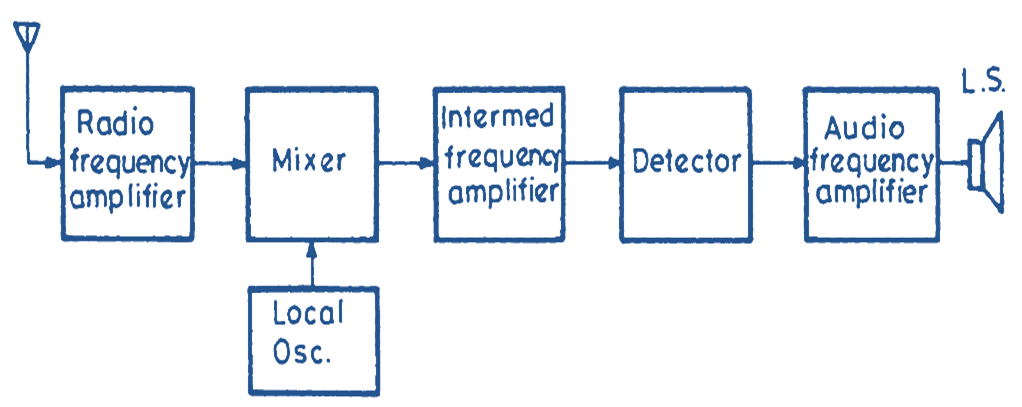
Fig. 1. Block diagram of a superheterodyne receiver.
Fig. 1 gives the block diagram of a superheterodyne receiver. The circuit consists of the following stages.
(i) RF Amplifier: An RF amplifier is a tuned voltage small signal amplifier tuned to the desired signal. The receiver aerial picks up various signals present in the free space. It converts these waves into electrical signals and passes these signals to the input of the RF amplifier. The aerial is unable to differentiate between different signals.
The tuned circuits in RF amplifier perform the function of selecting the desired signal and rejecting the other signals. For this, the tuned circuits in the amplifier are tuned to the desired signal frequency. The desired signal is selected and amplified by the amplifier and given at the mixer input. The increased level of the signal at the input of the mixer improves the signal to noise ratio of the receiver.
(ii) Local Oscillator: It is a high frequency sinusoidal oscillator whose frequency is adjusted according to the frequency of the input signal such that local oscillator frequency f0 is above the signal frequency fS by 455 kHz. A variable capacitor is used for adjustment of the oscillation frequency. This variable capacitor is mounted on the same spindle on which the tuning capacitor of the RF amplifier is mounted so that the resonant frequency of the RF amplifier as well as the local oscillator frequency can be varied simultaneously. The output of the local oscillator is given to the mixer circuit.
(iii) Mixer: The mixer stage has two inputs—the modulated signal with frequency fS and the local oscillator frequency f0. The two signals are mixed and as a result various frequencies such as fS, f0, f0 + fS; f0-fS along with their harmonics are produced in the output current of the mixer. Since the load to the mixer is a parallel resonant circuit (tuned to 455 kHz), the mixer output developed across this resonant circuit corresponds to 455 kHz alone because for all other frequencies, the mixer load offers neglegible impedance.
(iv) Intermediate Frequency Amplifier: The output of the mixer which is a modulated wave having carrier frequency fC = 455 kHz is given to the IF amplifier. The IF amplifier is a tuned voltage amplifier which is designed to operate at 455 kHz. Since this amplifier is designed to amplify modulated waves; it possesses a bandwidth of 10 kHz, it amplifies equally all frequencies lying between 450 kHz to 460 kHz. All signals lying above or below this frequency band are rejected. If amplifier provides very good rejection to the signals having frequency adjacent to the desired signal. In other words; this amplifier provides very good adjacent channel selectivity. To understand the reason for the improvement of adjacent channel selectivity by an IF amplifier; assume an input signal with frequency of 1 MHz ± 5 KHz. This signal is converted by the mixer to 455 kHz ± 5 KHz. To receive these signals, the bandwidth required by the IF amplifier is,
\[\text{Percentage Band Width}=\frac{\pm 5\text{ KHz}~}{455\text{ KHz}}\text{ }\!\!~\!\!\text{ }\times \text{100}\]
\[=\text{ }\pm \text{ 1}\text{.1 }
If a straight receiver with R.F amplifiers having a bandwidth of ± 1.1
\[\text{1MHz}\pm \frac{\text{1}\text{.1}}{\text{100}}\text{ }\!\!~\!\!\text{ }\times \text{1MHz}=\text{ }\pm \text{11KHz}\]
This receiver will pass frequencies from 989 kHz to 1011 kHz to its output. The straight receiver will therefore not only pass the desired modulated signal but will also allow modulated signals having frequencies close to the frequency of the desired signal.
(v) Detector: Signal output from the IF amplifier is fed to the detector. The detector demodulates the modulated IF signals and gives the audio signal at its output. The detector stage most commonly used is the linear diode detector because it introduces very low distortion and provides excellent audio fidelity. The DC component present in the detector output is used as automatic gain control bias to control the gain of the IF and RF amplifier stages.
(vi) AF Amplifier: The audio signal obtained from the output of the detector has a low magnitude. This signal is given to a small signal audio amplifier which increases the level of the audio to the desired magnitude. The final stage in the AF amplifier is the AF power amplifier and the output of this amplifier drives the loudspeaker. The loudspeaker converts the audio signals into sound waves.