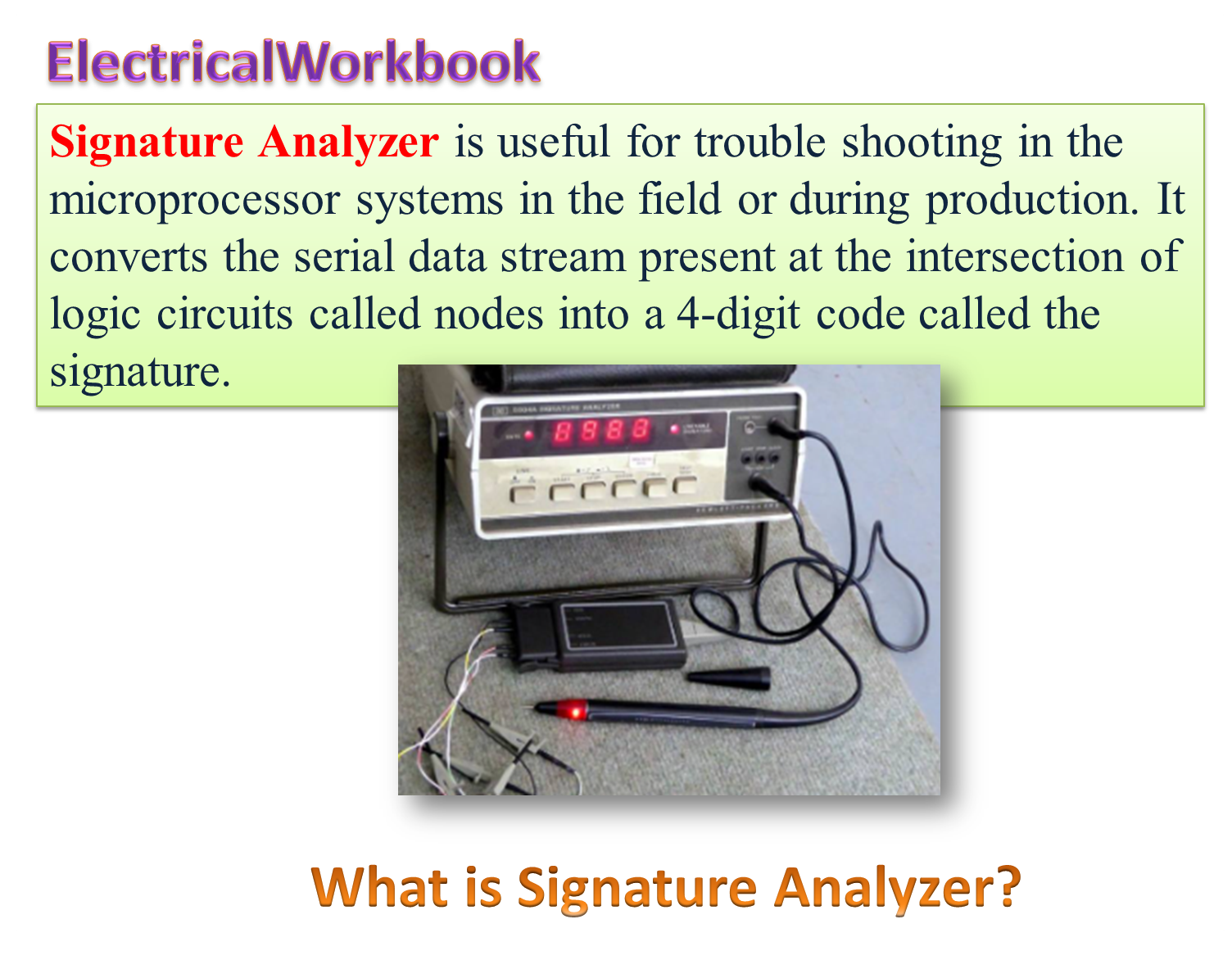
While analyzing an analog circuit, the waveform on a CRO is observed at the test point. By comparing this waveform with the actual waveform expected in a healthy circuit, we can identify the fault. In digital circuits, this process will not work as the train of pulses representing binary codes (0, 1) look very similar to each other. Hence, while fault location in digital circuits, a train of pulses at the test point is converted into a recognizable form such as in Hexadecimal number. The recognizable form is called a “signature” and the technique is called as “signature analysis”. Therefore the fault location is reduced just to feed the appropriate input data and testing for the “signature” obtained at the output or test point.
Block diagram of Signature Analyzer
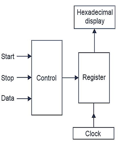
Fig. 1. Block diagram of Signature Analyzer.
The block diagram of a signature analyzer is shown in Fig. 1, giving the START signal. A register begins the process of capturing data bits. By giving STOP signal, this process is stopped after a time determined by CLOCK. The data bits captured by the register are displayed by a “hexadecimal signature.”
Test programs are written for various parts of the circuit. Now the signature analyzer is used to test the correct signature. The signature analyzer may have facility to store good “signature” to make comparison. An incorrect signature will indicate a fault.