After reading this Superposition theorem topic of electric or network circuits, you will understand the theory, limitations, also able to apply it in ac and dc circuits numerical problems.
Superposition theorem states that in a linear bilateral network containing more than one independent source, the response in any element is the sum of the response obtained with one source acting at a time and other source being deactivated. Deactivation means all the independent sources are replaced by their internal resistances i.e. voltage source replaced by a short circuit and current source replaced by an open circuit while retaining all the dependent sources as they are.
Procedure (steps) for applying Superposition Theorem:-
- Select any one independent source and do the calculation for voltage or current due to this source.
- Repeat step-1 for each independent source.
- Algebraically add the results of each source.
Superposition theorem Example based on the DC circuit
Q For the given network, find the current I using superposition theorem. 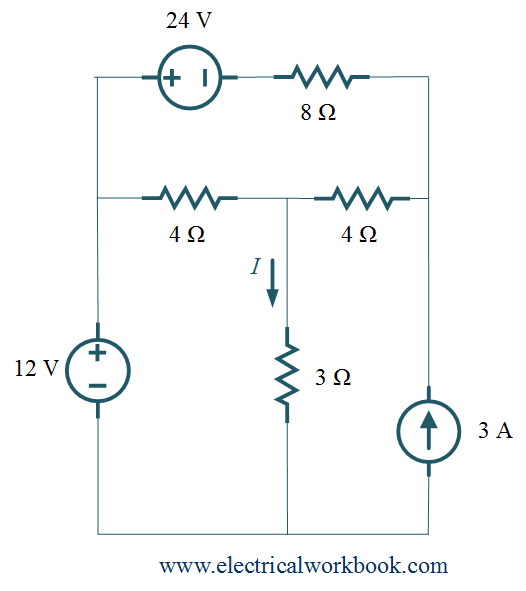
Solution:
Step 1: – Consider 12 V voltage source, replace 24 V voltage source as a short circuit and 3 A current source as an open circuit in Figure 1.
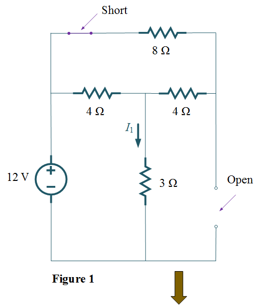
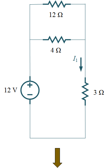
Thus,
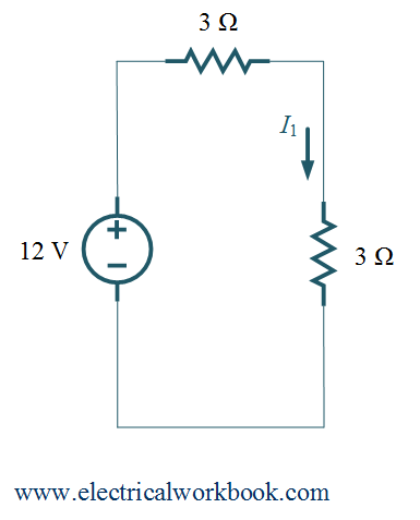
\[{I_1} = \frac{{12}}{6} = 2{\text{ A}}\]
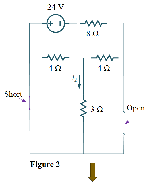
Step 2: – Consider 24 V voltage source, replace 12 V voltage source as a short circuit and 3 A current source as an open circuit, shown in Figure 2.
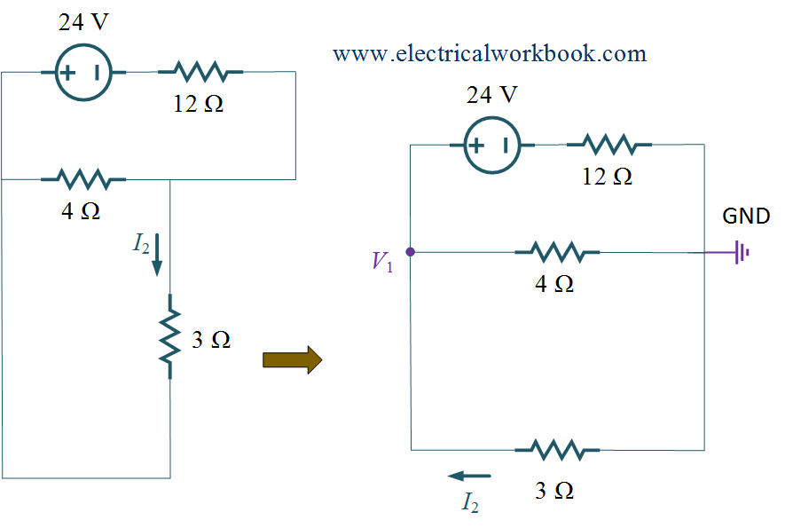
Then, Apply KCL to node 1, we get
\[\frac{{{V_1} – 24}}{{12}} + \frac{{{V_1}}}{4} + \frac{{{V_1}}}{3} = 0\]
\[{\text{or, 8}}{V_1} = 24\]
\[{\text{or, }}{V_1} = 3{\text{ V}}\]
\[{I_2} = \frac{{0 – {V_1}}}{3} = \frac{{ – 3}}{3} = – 1\]
\[{\text{Thus, }}{I_2} = – 1{\text{ A}}\]
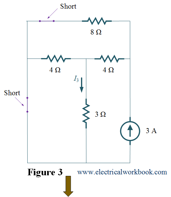
Repeat step 2: – Consider 3 A current source, replace 24 V voltage source as short circuit and 12 V voltage source as short circuit, shown in Figure 3.
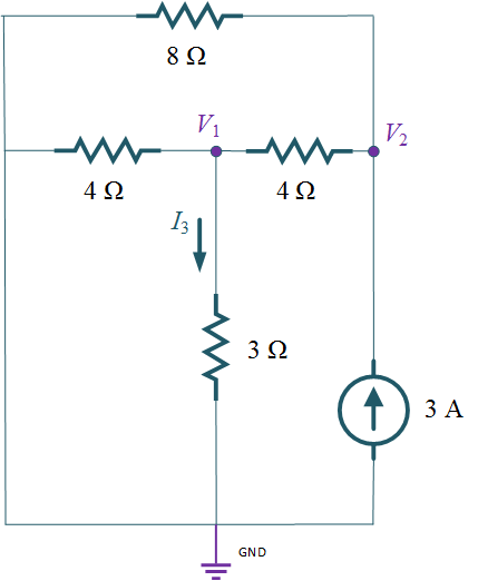
Then, Apply KCL to node 1,we get
\[\frac{{{V_1}}}{4} + \frac{{{V_1}}}{3} + \frac{{{V_1} – {V_2}}}{{12}} = 0\]
${\text{or, }}3{V_2} = {\text{10}}{V_1}$ …..(1)
Apply KCL to node 2,we get
\[\frac{{{V_2}}}{8} + \frac{{{V_2} – {V_1}}}{4} – 3 = 0\]
\[{\text{or, }}\frac{{{V_2}}}{8} + \frac{{{V_2} – {V_1}}}{4} = 3\]
${\text{or, }}3{V_2} – 2{V_1} = 24$ …..(2)
Put Eq.(1) in Eq.(2), we get
\[10{V_1} – 2{V_1} = 24{\text{ }}\]
\[{\text{or, }}{V_1} = 3{\text{ V}}\]
\[{I_3} = \frac{{{V_1}}}{3} = \frac{3}{3} = 1\]
${\text{Thus, }}{I_3} = 1{\text{ A}}$
Step 4:- By applying superposition theorem,
\[I = {I_1} + {I_2} + {I_3}\]
\[{\text{or, }}I = 2 – 1 + 1\]
\[I = 2{\text{ A}}\]
Superposition theorem Example based on AC circuit
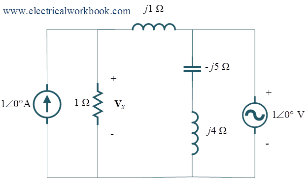
Q For the given network, find the voltage Vx using superposition theorem.
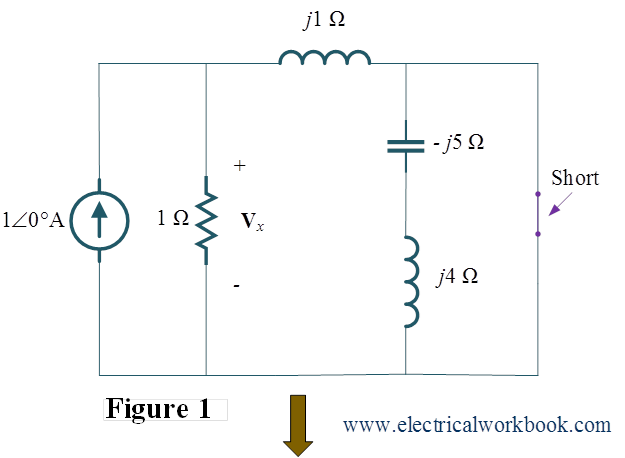
Step 1: – Consider $1\angle 0^\circ$ A current source, replace $1\angle 0^\circ$ V voltage source as short circuit, shown in Figure 1.
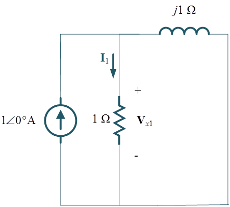
Then, by applying current division to find ${{\mathbf{I}}_1}$, we get
\[{{\mathbf{I}}_1} = \frac{{1\angle 0^\circ \times j}}{{1 + j}}\]
\[{{\mathbf{V}}_{x1}} = {{\mathbf{I}}_1} \times 1\]
\[{\text{or, }}{{\mathbf{V}}_{x1}} = \frac{{1\angle 0^\circ \times j}}{{1 + j}} \times 1\]
\[{\text{or, }}{{\mathbf{V}}_{x1}} = \frac{j}{{1 + j}}{\text{ V}}\]
Step 2: – Consider $1\angle 0^\circ$ V voltage source, replace $1\angle 0^\circ$ A current source as open circuit, shown in Figure 2.
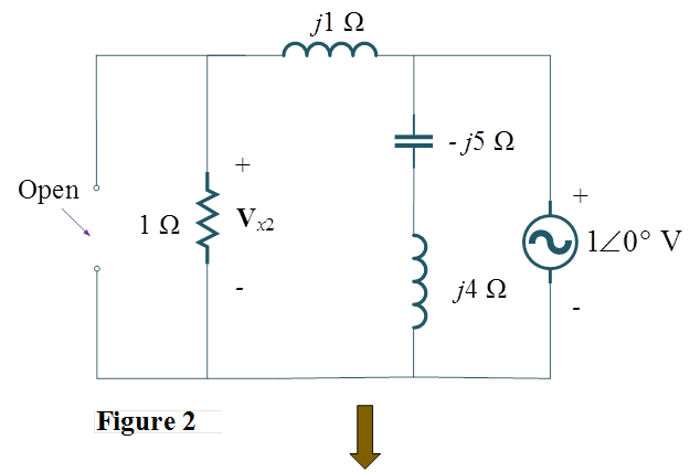
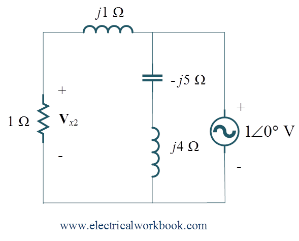
Then apply voltage division rule we get,
\[{{\mathbf{V}}_{x2}} = \frac{{1\angle 0^\circ \times 1}}{{1 + j1}}\]
\[{\text{or, }}{{\mathbf{V}}_{x2}} = \frac{1}{{1 + j}}{\text{ V}}\]
Step 3: – By applying superposition theorem,
\[{{\mathbf{V}}_x} = {{\mathbf{V}}_{x1}} + {{\mathbf{V}}_{x2}}\]
\[{\text{or, }}{{\mathbf{V}}_x} = \frac{j}{{1 + j}} + \frac{1}{{1 + j}} = \frac{{1 + j}}{{1 + j}} = 1\angle 0^\circ \]
\[{\text{Thus, }}{{\mathbf{V}}_x} = 1\angle 0^\circ {\text{ V}}\]
Limitations
- Superposition theorem is not applicable in case of Nonlinear networks and for the parameters which show nonlinear relationship like power.
- When it applied on a circuit, direction (sign) of currents supplied by each source should be noticed.