After reading this AC supply to pure inductor topic of electric or network circuits, you will understand the theory, waveforms, inductive reactance, phasor, formula, & also voltage, current, power calculation.
Voltage and Current Relationship
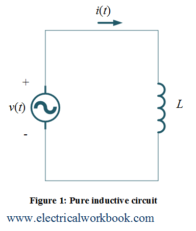
Let us consider a circuit having inductor L supplied by an ac source voltage $v(t)$ which produce a sinusoidal current $i(t)$ as shown in Figure 1 is
$i(t) = {I_m}\sin \omega t$ ….(1)
The general expression that relates inductor voltage and current is
\[v(t) = L\frac{{di(t)}}{{dt}}{\text{ }}…(2)\]
Put equation (1) in equation (2),
\[v(t) = L\frac{d}{{dt}}\left( {{I_m}\sin \omega t} \right)\]
\[ = \omega L{I_m}\cos \omega t\]
\[ = \omega L{I_m}\sin \left( {\omega t + 90^\circ } \right)\]
\[ = j\omega L{I_m}\sin \omega t\]
Thus,
$v(t) = j\omega L{I_m}\sin \omega t$ ….(3)
we know,
\[v(t) = \omega L{I_m}\cos \omega t = {V_m}\cos \omega t\]
where, ${V_m} = \omega L{I_m}$
Phasor diagram
The phasor representation of Equations (1) and (3), is shown in Figure 2, can be written and relate in phasor terms as
\[{\mathbf{V}} = j\omega L{\mathbf{I}} = j{X_L}{\mathbf{I}}\]
where ${X_L} = \omega L$ and called as inductive reactance. Equations (1) and (2) shows that current lags voltage by phase angle of ${\text{90}}^\circ$ so waveforms will look as shown in Figure 3.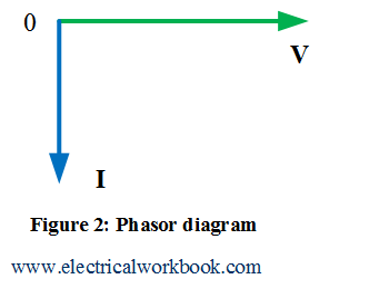
Power calculation
The instantaneous power $p(t)$ is defined by the product of instantaneous voltage $v(t)$ and instantaneous current $i(t)$.
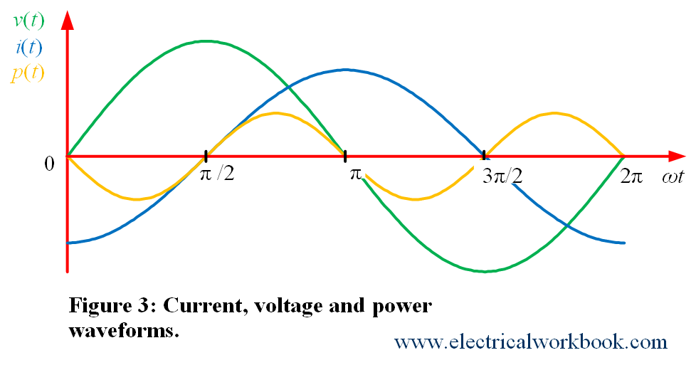
The instantaneous power $p(t)$ waveform shown in Figure 3. And according to the definition, instantaneous power $p(t)$ write as
$p(t) = v(t)i(t)$ ….(4)
Using Equation (4), the average power is defined as
\[{P_{av}} = \frac{1}{T}\int\limits_0^T {p(t)dt} \]
Also,
\[{P_{av}} = \frac{1}{T}\int\limits_0^T {v(t)i(t)dt} \]
\[ = \frac{1}{T}\int\limits_0^T {\left( {{V_m}\cos \omega t} \right)\left( {{I_m}\sin \omega t} \right)dt} \]
\[ = \frac{{{V_m}{I_m}}}{T}\int\limits_0^T {\sin \omega t\cos \omega tdt} \]
\[ = \frac{{{V_m}{I_m}}}{{2T}}\int\limits_0^T {2\sin \omega t\cos \omega tdt} \]
\[ = \frac{{{V_m}{I_m}}}{{2T}}\int\limits_0^T {\sin 2\omega tdt} \]
\[ = 0\]
Thus,
\[{P_{av}} = 0.\]
Also, Figure 3 shows that the frequency of instantaneous power ${f_p}$ is twice the frequency of instantaneous voltage ${f_v}$ or the frequency of instantaneous current ${f_i}$ as
\[{f_p} = 2{f_i}{\text{ }}or{\text{ }}2{f_v}\]
Note:- In the first half cycle of the instantaneous power $p(t)$, the inductor takes the energy from the source and in the second half cycle of the instantaneous power $p(t)$, inductor delivers the energy back to the source.