In this topic, you study Three phase Wattmeter – Working, Construction & Diagram.
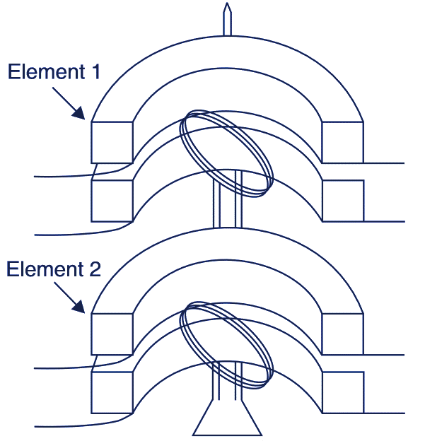
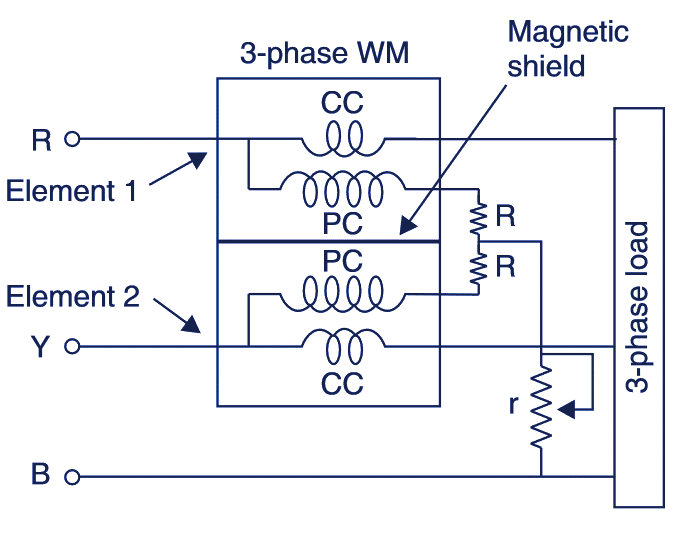
Three phase Wattmeter is dynamometer type and consists of two separate wattmeters mounted together in the same case. There are two current coils (CC) and two pressure coils (PC). Both the moving coils (PCs) are rigidly coupled axially by a rod of insulating material. A “CC along with PC” is known as “one element” therefore a 3 phase wattmeter has two elements. The connections of two elements of the 3 phase wattmeter are similar as in “Two wattmeter method’ used for measuring 3 phase power. The deflecting torque on CC of each element is proportional to the power being measured. Hence, the total deflecting torque on both the elements will be proportional to the sum of the two powers. See Fig. 1.

Fig. 1. Three phase Wattmeter
Deflecting torque on the first element.
Td1 ∝ P1
Deflecting torque on the second element.
Td2 ∝ P2
where are P1 and P2 powers.
Thus, Total deflecting torque
Td1 + Td2 = Td1 ∝ (P1+ P2) ∝ P
where P is total power.
In order, that the 3 phase wattmeter reads correctly, there should not be any mutual interference between the two elements. For this purpose, a nickel iron plate may be placed between the two elements as a magnetic shield or the two moving coils be mounted at right angles. However, a resistance r may be used for adjustment against errors caused by mutual interference. See Fig. 1.

Fig. 2. Connections of Three phase Wattmeter.
Advantages of Three phase Wattmeter
The advantage of this instrument is that the total power consumed by a 3 phase load is obtained by direct reading or the single instrument instead of adding two readings in two wattmeter method.
Disadvantages of Three phase Wattmeter
The disadvantage of such an instrument is that it is not so accurate as a single phase wattmeter.