In this topic, you study Dynamometer Type Wattmeter – Working, Construction & Diagram.
Dynamometer Type Wattmeter is similar to the dynamometer type ammeters and voltmeters. The dynamometer instruments are used more as wattmeters, as they are expensive (Fig. 1.).
The fixed coil which is divided into two equal coils is used as ‘”current coil (CC) ” and the moving coil is used as a “pressure coil (PC). The current coil carries full load current, whereas the pressure coil carries a current proportional to the voltage across the circuit. The moving coil carries a pointer. The interaction of the magnetic fields of the current coil and sure coil produces a torque and makes the pressure coil to move. The pointer attached with it also moves and gives deflection on a calibrated scale. The controlling torque is produced by springs and damping torque by air damping.
Note that the “Fixed coil” is also called as “current coil”. The moving coil also called potential coil/voltage coil.
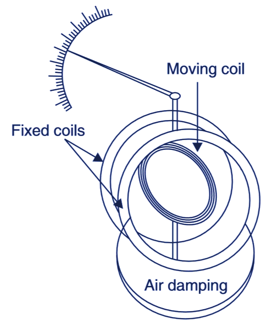
Fig. 1. Dynamometer Type Wattmeter.
The Fig. 2 shows connections of wattmeter to measure power. The high impedance CC is connected in series and low impedance PC is connected in parallel. This reduces error and the instrument is called compensated wattmeter.
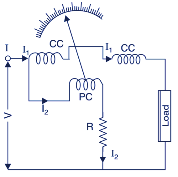
Fig. 2. Wattmeter Connections.
The Fig. 3 shows practical connections of the wattmeters in the laboratory. The M and L are the terminals of current coil (Fixed coil). The M is to be connected with the “SUPPLY” and L with the “load”.
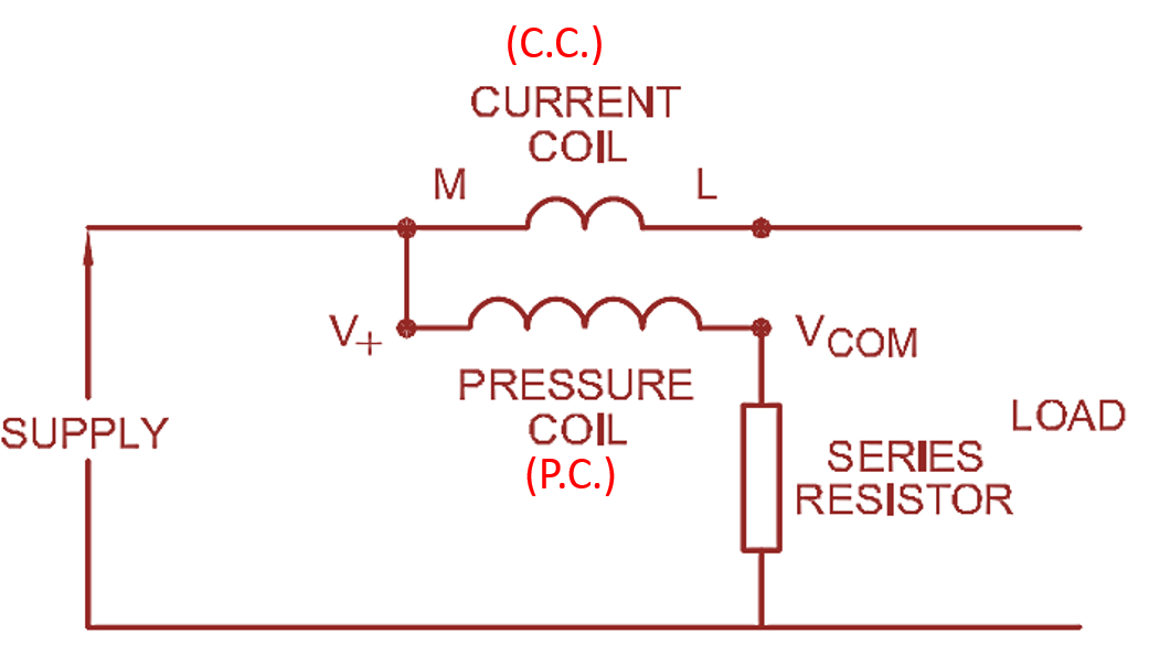
Fig. 3: Connection of Dynamometer Type Wattmeter.
Torque in Dynamometer Type Wattmeter
Assuming If and Im are the currents flowing through the fixed and moving coils of Wattmeter (See Fig. 4).
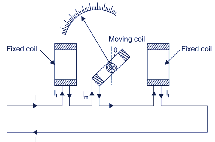
Fig. 4. Torque in Dynamometer Type Wattmeter
Deflecting torque Td ∝ If . Im and controlling torque Td ∝ θ where θ is the angle of deflection of the moving coil.
In steady position
TC = Td
θ ∝ If . Im
or
θ ∝ I2
Since, If ∝ I and Im ∝ I
Advantages of Dynamometer Type Wattmeter
- It can be used for ac/dc power measurements.
- Due to spring control, the scale of the instrument is uniform.
- The instrument can give a high degree of accuracy
Disadvantages of Dynamometer Type Wattmeter
- The instrument is expensive, but the high accuracy obtained compensates this disadvantage.
- Its accuracy is affected by the external magnetic fields, hence it must be screened.
- At low power factors, the inductance of the pressure coil (P.C) introduces a serious error.
For minimizing this error, the inductance of the pressure coil may be reduced by connecting a high resistance in series with it and connecting a capacitor across a part of this resistance. The error can further be reduced by connecting an additional winding called “compensating winding” in series with the pressure coil and so placed that it produces a field in the opposite direction to that of the current coil.
Types of Dynamometer Type Wattmeter
The dynamometer wattmeters are of two types :
Suspended coil torsion head type wattmeter: These wattmeters have a suspended coil from a torsion head through a metallic strip which acts also “leads” to the coil. The torsion head is provided with a scale. These instruments are used for standardization and calibration purposes in the laboratories for standardization and calibration purposes in the laboratories.
Pivoted coil direct reading wattmeter: These wattmeters have a coil pivoted between fixed coil wound in two halves and placed at a distance parallel to each so that a uniform magnetic field is obtained. The magnetic axis of the pivoted moving coil and the two halves of the fixed coil is same. The instruments are direct indicating instruments and are used as portable/switch board instruments.
Note: Dynamometer type instruments are widely used as “power factor meter”, synchronoscope etc.
Errors in Dynamometer Type Wattmeter
The main sources of errors and to keep them minimum is described below:
Low torque/weight ratio: The magnetic field produced by air cored coils is small, therefore deflecting torque of these instruments is low. To have high magnetic field and thus high torque, the moving coil has to be heavy. This increases torque weight ratio, which causes frictional errors which are very high.
Frequency: The frequency enors in these instruments are large due to variation of self inductance of the coils with the fiequency.
Eddy currents: Eddy currents are induced in any metal part adjacent to the moving system. This will produce errors. For this, the metal parts are kept minimum and that too are placed away from the moving system.
Stray magnetic fields: The stray magnetic fields surrounding the instrument, badly effect the accuracy, hence the instrument must be provided with magnetic shield.
Temperature: High currents are carried by the coils which produce heat and cause errors. For tuis, compensating coils (inductance) are used to keep the error minimum.
Power loss in the coils: There is a power loss in the current coil and potential coil. This also causes some error in the reading.
Inductance of potential coil: The inductance of the potential coil is also a source of error in the wathueter reading. Due to this error, the wattmeter gives high reading on lagging power factor and vice-versa. A swamping resistance in series with the potential coil reduces this error