In this topic, you study Wattmeter Connection – Diagram, Working & Methods.
These are two methods of connecting a wattmeter in the circuit to measure power.
(a) In the connections shown in Fig. 1. (a) the pressure coil (P.C.) is connected on the supply side and the voltage applied to the P.C is equal to the sum of the voltages across the load and the voltage drop across the current coil (C.C.). Therefore, the wattmeter will read the power consumed by the load plus power loss in the current coil.
(b) In the connections shown in Fig. 1. (b), the C.C. is connected on the supply side and will carry the load current plus the current in the P.C. Therefore, the wattmeter will read the power consumed in the load plus power loss in the P.C. If the load current is small the connections shown in Fig 1. (a) are preferred but if the load is larger, the connections shown in Fig 1. (b) are preferred.
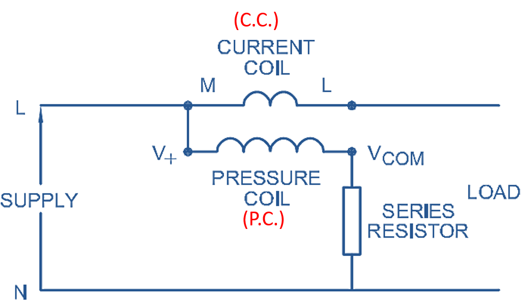
(a)
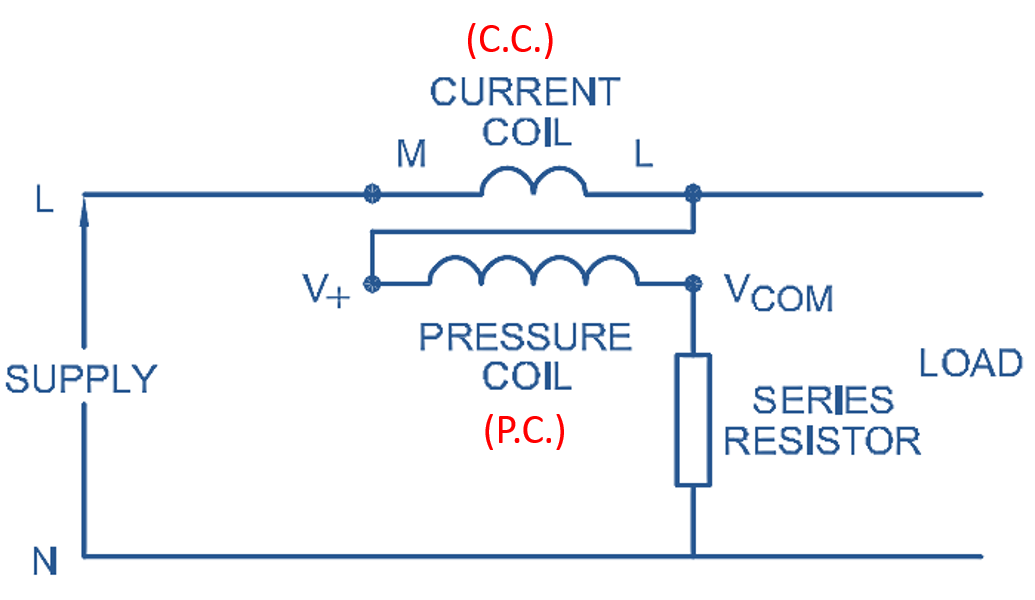
(b)
Fig. 1. Wattmeter Connections in the Circuit.