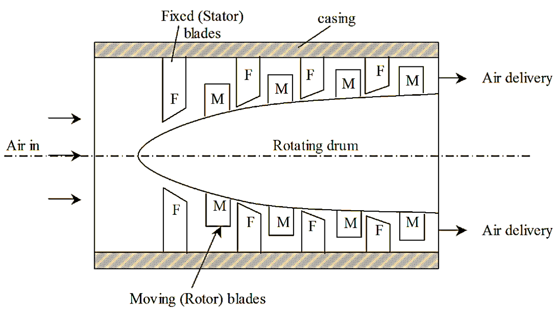
An axial flow compressor consists of adjacent rows of fixed (stator) and moving (rotor) blades. A set of fixed and moving blades is called as a stage of compressor. In this type of compressor, the flow of air is in axial direction of the machine. The fixed or stator blades are fixed to the casing and the moving of rotor blades are mounted on the rotating drum as shown in figure 1.

Figure 1: Axial Flow Compressor
The blades are so arranged that the space between them forms diffuser passages. In order to keep the flow velocity constant, the annular area is reduced from the inlet to the outlet of the compressor. During its working, the work input is provided to the rotor shaft, which transfers its energy to the moving of rotor blades.
This heads to the acceleration of air. The blades are designed to reduce the losses due to turbulence and shock. The design is based on the aerodynamic theory and the blades are of aerofoil section. The velocity thus increases due to the reduction in acceleration of air in the space between the rotor and the stator whereas increases the pressure energy due to diffùsion action. The stator blades perform another function of redirecting the air to the succeeding rotor at an angle suitable for entry. A single stage of the axial flow compressor gives a maximum pressure ratio about 1.12 to 1.2 in order to obtain higher pressure ratio (say 12), 15 to 20 stages of compression are required. The blades are so arranged to have an equal temperature rise in the blades and to keep the velocity of air constant. Generally, there are two types of rotors used. They are.
- Drum type (used for static industrial applications).
- Disc type (used where low weight is considered irrespective of cost).
The materials used for the rotor blading are fibrous composites, Aluminium, Titanium, Steel, Nickel alloy and that for the stator blading is mostly steel. Castings are generally made from Magnesium, Aluminium. Steel, Iron or fabricated form of Titanium or steel.