A system in which input has a command over the output or a system in which input has a control over the output is called a control system. A water tap can be taken as simple and best example of a control system. Here the flow of water (i.e., the output) is mechanically controlled by the movement of valve (i.e., input). The diagrammatic representation of simple control system is shown below
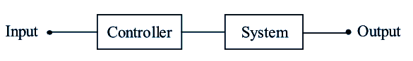
Figure (1): A Control System
Examples of Control Systems
Different examples of control systems are,
A Switch
One among the examples of a control system is a switch in which the input is mechanically pressing or applying force on button with the fingers and output is flow or non-flow of current. The diagrammatic representation is shown below
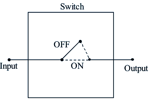
Figure (2): A switch
A Driving System
Here the input is the Acceleration which is given by a human being to the vehicle which controls or regulates the output i.e., the speed of the vehicle. The desired speed can be obtained by controlling the Acceleration. The diagrammatic representation is shown below
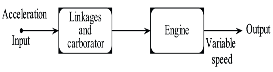
Figure (3): Driving System of an Automobile
Biological Control System
In this system a person with his finger points towards a particular object and the output is desired pointed direction. The control signal here is the position of the object. The diagrammatic representation is shown below
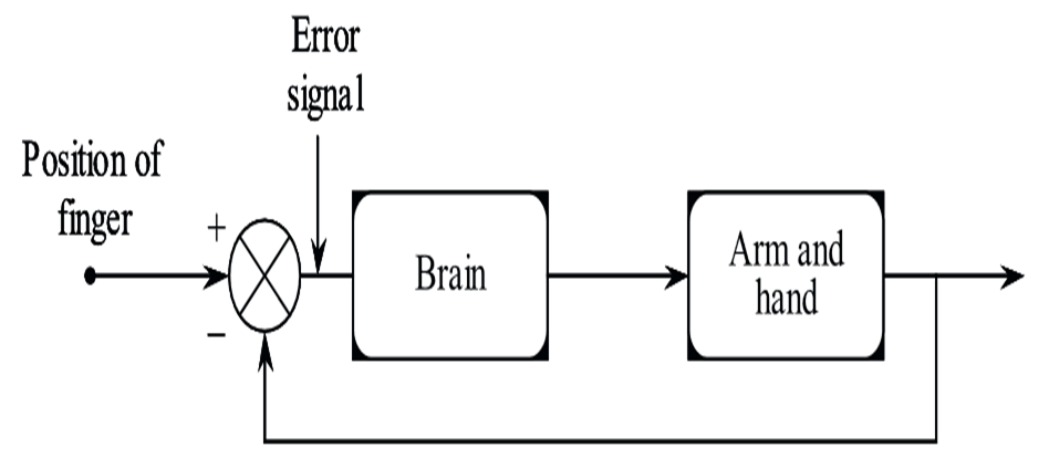
Figure (4): Biological Control System.
Examples of control system include temperature measurements of thermometer, refrigerator, washing machine, electric frying pans, household devices with thermoset like iron etc.
Elements of a Control System
In a system where, the variations in the output quantity are continuously measured through feedback and compared by the input quantity, then such a system is called ‘control system’. The reference input is the excitation signal given to the system. It is also called as command signal (or) excitation. The output quantity is the response obtained after the processing of the signal. It is also called as response (or) controlled variable. The basic components of control system are,
- Plant
- Feedback path elements
- Error detector
- Controller.
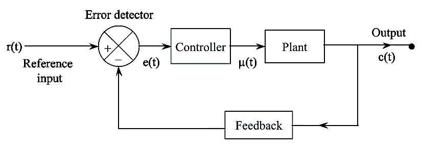
Figure: Block Diagram of Components Connected
The functioning of the component of the system shown in figure is,
Plant
It is a unit where actual processing is performed. The input to the plant is the control signal generated by the controller. The plant performs the necessary action on this signal and generates the desired output which is called as controlled signal.
Feedback
Feedback is a controlled action in which the sampled output is given to the input for automatic correction of output due to any changes or disturbances occurring in the system. Generally negative feedback is employed for controlling of systems as it provides accuracy, better stability and reject disturbances. The feedback signal is fed to the error detector.
Error Detector
The function of error detector is to generate error signal. There are two inputs to the error detector i.e., the feedback signal and the reference signal. The error detector generates an output which is the difference of these two signals. This error signal is fed to the controller for the necessary control action.
Controller
The controller modifies and amplifies the error signal so that, the signal is a bit modified. Now a modified signal is obtained by the controlled action of controller. The modified signal is then passed to the plant for output rectification so as to reduce the error signal.