Unloading valves are pressure control valves, used to discharge the excess fluid from the pump to the tank with a small or zero pressure drop. These valves are used in high-low pump circuit applications where two pumps are used to move an actuator at high speed and low pressure.
Types of Unloading Valves
Unloading valves are of two types. They are,
- Pilot operated unloading valve
- Direct acting unloading valve
Pilot Operated Unloading Valve
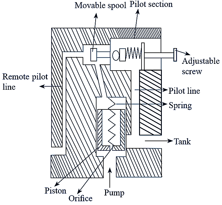
Figure 1: Pilot operated unloading valve.
This type of valve cannot allow the pump flow directly to the tank like the direct acting type valve. It is siiiìilar to the pilot-operated relief valve. The only difference is that a movable spool is used in pilot-operated unloadmg valve as an addition part. It consists of an inlet port and the outlet port connected to pump and tank respectively. A movable spool and spring loaded ball is placed in pilot section. A piston with spring load is placed in the main chamber and a narrow orifice is provided through the piston. A remote-pilot line is arranged inside the valve, connected to the pilot section. A pilot line is connected to the outlet port. A pilot-operated unloading valve is shown in figure 1. When the pressure in the circuit exceeds the valve setting, high pressure signals reach the unloading spool through remote-pilot port. Due to lower back force, spool moves rightward thereby, spring loaded ball opens completely. A small amount of fluid starts to flow to the tank through the pilot line and remaining fluid flows through the piston orifice. When the flow starts in the pilot line and the orifice, the pressure drop takes place across the piston. Due to pressure drop, the piston moves up against the spring force and the outlet port will open. Then, fluid flows freely from pump to the tank with small or zero pressure.
Direct Acting Unloading Valve
It consists of an adjustable spring moves in the control chamber and a movable spool held in closed position in the main chamber by the spring force. The inlet and outlet ports are connected to the pump and reservoir (tank) respectively. A drain is provided at control chamber to return the leaked fluid past the spool into the reservoir. It is a normally closed type valve, i.e., the outlet port is closed by the spool in normal condition, so that the spool offers the resistance to flow from the pump to the tank. Initially, the valve restricts the flow through outlet. The fluid from pump enters the external-pilot port with high pressure where the fluid offers a force against the pilot piston. When the pressure at the pilot port reaches to the spring load, the fluid will deviate from pump to tank. If the fluid pressure exceeds the spring force, then the spool in the main chamber moves against the spring force, thus, opening the outlet port. Then, the fluid flows directly to the reservoir through the outlet port with small or zero pressure.