Diesel cycle cycle is also known as constant pressure heat addition cycle as heat is added to the cycle at constant pressure. This cycle consists of four processes.
1. Isentropic compression process
2. Constant pressure heat addition process
3. Isentropic expansion process
4. Constant volume heat rejection process.
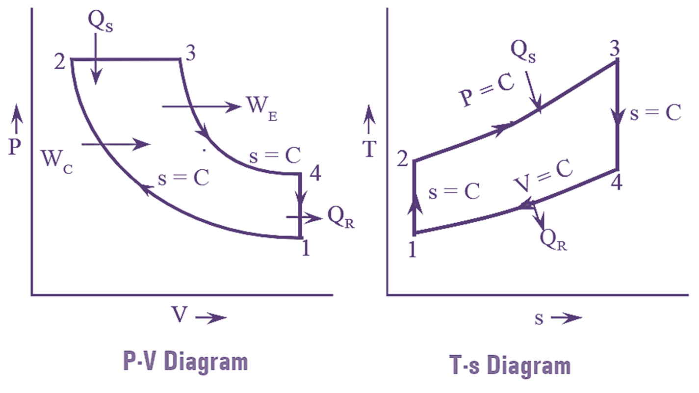
The representation of diesel cycle on P-V and T-s diagram is shown in below figure 1,

Figure 1: Diesel Cycle.
Isentropic Compression Process: During this process, the air in the cylinder is compressed by moving the piston from B.D.C to T.D.C. Since, it is an isentropic process, there will be no heat transfer and hence the entropy remains constant. This process is represented by the line 1-2 in P-V and T-s diagram. Due to compression, the pressure and temperature in the cylinder increases. The ratio of initial volume to the volume after compression $\left( \frac{{{V}_{1}}}{{{V}_{2}}} \right)$ is known as compression ratio.
Constant Pressure Heat Addition Process: In this process, the compressed air which is at high pressure is heated with the help of constant addition. This process is represented by the line 2-3 in P-V and T-s diagram. After completion of this process, the temperature reaches its highest point in the cycle. Thus, entropy of air also increases. During this process the volume of air increases and the ratio of volume of air after heat addition to the volume of air before heat addition $\left( \frac{{{V}_{3}}}{{{V}_{2}}} \right)$ is known as cut-off ratio.
Isentropic Expansion Process: In this process, the high pressure and temperature air is expanded isentropically. Due to this, the pressure and temperature of air decreases. Expansion takes place till the piston reaches B.D.C work is produced during expansion and it is called the power stroke. The line ‘3-4’ represents this process on P-V and T-s diagram.
Constant Volume Heat Rejection Process: In the expansion process, the piston reaches to B.D.C and from there it can’t move further. So the hot air is the cylinder rejects heat at constant volume to achieve equilibrium with the surrounding, after rejecting heat the air reaches to its initial condition. The line ‘4-1’ in P-V and T-s diagram represent this process. As heat is rejected the entropy of the air also decreases. This completes the cycle and it is repeated.
Heat added in the cycle,
QS = Q2-3 = CP (T3 – T2)
Heat rejected in the cycle,
QR = Q4-1 = Cv (T4 – T1)
Workdone per cycle,
W = QS – QR
= CP (T3 – T2) – Cv (T4 – T1)
Thermal efficiency,
\[{{\eta }_{th}}=\frac{W}{{{Q}_{S}}}\]
\[=\frac{{{C}_{p}}({{T}_{3}}-{{T}_{2}})-{{C}_{v}}({{T}_{4}}-{{T}_{1}})}{{{C}_{p}}({{T}_{3}}-{{T}_{2}})}\]
\[{{\eta }_{th}}=1-\frac{1}{\gamma }\left( \frac{({{T}_{4}}-{{T}_{1}})}{({{T}_{3}}-{{T}_{2}})} \right)\]
Air standard efficiency of a Diesel Cycle
Diesel cycle is also known as constant pressure heat addition cycle. It consists of four reversible processes. They are,
- Isentropic compression process.
- Constant pressure heat addition process.
- Isentropic expansion process.
- Constant volume heat rejection process.
The P-V and T-s diagram of diesel cycle is shown below.
Heat supplied to the cycle,
QS = Q2-3 = CP (T3 – T2)
Heat rejected from the cycle.
QR = Q4-1 = CV (T4 – T1)
Workdone per cycle,
W = QS – QR
= CP (T3 – T2) – CV (T4 – T1).
Thermal efficiency of diesel cycle,
\[{{\eta }_{th}}=1-\frac{1}{\gamma }\left( \frac{({{T}_{4}}-{{T}_{1}})}{({{T}_{3}}-{{T}_{2}})} \right)\]
\[{{\eta }_{th}}=\frac{Work\text{ }done}{Heat\text{ }added}\]
\[=\frac{{{C}_{p}}({{T}_{3}}-{{T}_{2}})-{{C}_{v}}({{T}_{4}}-{{T}_{1}})}{{{C}_{p}}({{T}_{3}}-{{T}_{2}})}\]
Since,
\[\frac{{{C}_{p}}}{{{C}_{v}}}=\gamma \]
\[=1-\frac{1}{\gamma }\left( \frac{({{T}_{4}}-{{T}_{1}})}{({{T}_{3}}-{{T}_{2}})} \right)\]
From isentropic process ‘1-2’,
\[\left( \frac{{{T}_{2}}}{{{T}_{1}}} \right)={{\left( \frac{{{V}_{1}}}{{{V}_{2}}} \right)}^{\gamma -1}}={{\left( r \right)}^{\gamma -1}}\]
Where,
\[r=\frac{{{V}_{1}}}{{{V}_{2}}}\]
r known as as compression ratio
\[{{T}_{2}}={{T}_{1}}{{\left( r \right)}^{\gamma -1}}\]
From constant pressure process ‘2-3’,
\[\frac{{{T}_{3}}}{{{T}_{2}}}=\frac{{{V}_{3}}}{{{V}_{2}}}=\rho \]
Where, ρ is cut off ratio
Therefore,
\[{{T}_{3}}={{T}_{2}}\rho \]
\[={{T}_{1}}{{\left( r \right)}^{\gamma -1}}\rho \]
From isentropic process ‘3-4’,
\[\frac{{{T}_{4}}}{{{T}_{3}}}={{\left( \frac{{{V}_{3}}}{{{V}_{4}}} \right)}^{\gamma -1}}\]
\[{{T}_{4}}={{V}_{3}}{{\left( \frac{{{V}_{3}}}{{{V}_{2}}}\times \frac{{{V}_{2}}}{{{V}_{4}}} \right)}^{\gamma -1}}\]
But,
\[\frac{{{V}_{3}}}{{{V}_{2}}}=\rho \]
And
\[\frac{{{V}_{2}}}{{{V}_{4}}}=\frac{{{V}_{2}}}{{{V}_{1}}}=\frac{1}{\gamma }\]
Since,
\[\text{ }{{V}_{2}}={{V}_{4}}\]
\[{{T}_{4}}={{T}_{3}}{{\left( \frac{\rho }{r} \right)}^{\gamma -1}}\]
\[{{T}_{4}}={{T}_{1}}{{r}^{\gamma -1}}\rho {{\left( \frac{\rho }{r} \right)}^{\gamma -1}}\]
\[{{T}_{4}}={{T}_{1}}{{\rho }^{\gamma }}\]
Substitute equations (2),(3) and (4) in eq. (1),
\[{{\eta }_{th}}=1-\frac{1\left( {{T}_{1}}{{\rho }^{\gamma }}-{{T}_{1}} \right)}{\gamma \left( {{T}_{1}}{{r}^{\gamma -1}}\rho -{{r}^{\gamma -1}} \right)}\]
\[1-\frac{1\left( {{\rho }^{\gamma }}-1 \right)}{\gamma \left( {{r}^{\gamma -1}}\rho -{{r}^{\gamma -1}} \right)}\]
\[ {{\eta }_{th}}=1-\frac{1}{{{r}^{\gamma -1}}}\left[ \frac{{{\rho }^{\gamma }}-1}{\gamma \left( \rho -1 \right)} \right]\]
Therefore, the efficiency of diesel cycle depends on compression ratio and cut-off ratio. The efficiency can be increased by increasing the compression ratio and decreasing the cut-off ratio. For the same compression ratio, diesel cycle efficiency is less than otto cycle efficiency.
Q. Name the factors that affect the air standard efficiency of Diesel Cycle.
The following factors affect the air standard efficiency of diesel cycle.
- Compression Ratio: Increase in compression ratio (r), increases the air standard efficiency of diesel cycle.
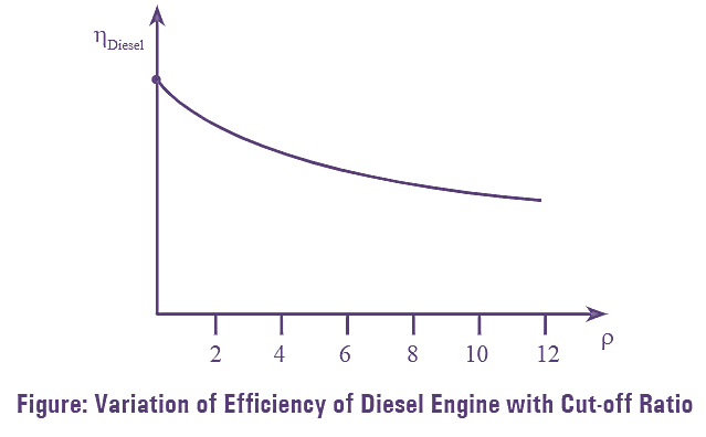
- Cut-off Ratio: Increase in cut-off ratio (ρ), decreases the air standard efficiency of diesel cycle.
- Adiabatic Index: For large values of adiabatic index (γ), air standard efficiency is high.
Q. When compression ratio is kept constant, what is the effect of cut-off ratio on the efficiency of diesel cycle.
Cut-off ratio (ρ) is defined as the ratio of initial and final volumes of air during constant pressure heat addition process. For same compression ratio (r) and adiabatic index (γ), the air standard efficiency of diesel cycle decreases with increase in cut-off ratio. The relation between cut-off ratio and air standard efficiency at constant r. γ values is shown in below figure,

Q. Explain with the help of suitable graphs the variation of the efficiency of the diesel cycle with compression ratio and cut-off ratio.
The equation relating thermal efficiency (ηth), compression ratio (r) and cut-off ratio (ρ) for diesel cycle is shown below,
\[{{\eta }_{th}}=\frac{1}{{{r}^{\gamma -1}}}\left[ \frac{{{\rho }^{\gamma -1}}}{\gamma \left( \rho -1 \right)} \right]\]

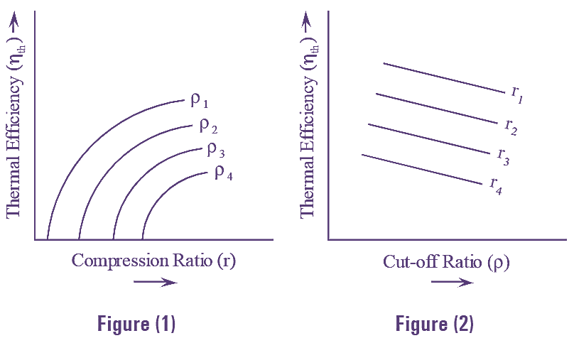
Graphs are drawn between compression ratio (r) and thermal efficiency (ηth) and also between cut-off ratio (ρ) and thermal efficiency (ηth).
Figure (1) is drawn between compression ratio (r) and thermal efficiency (ηth) for different values of cut-off ratio (ρ). From the graph, it can be seen that, for different values of cut-off ratio (ρ) the thermal efficiency (ηth) increases with the increase in compression ratio (r). When cut-off ratio (p) is unity, then the efficiency of diesel cycle is equal to the efficiency of Otto cycle.
Figure (2) is drawn between cut-off ratio (ρ) and thermal efficiency (ηth) for different values of compression ratio (r). As the value of cut-off ratio (ρ) increases, the thermal efficiency of diesel cycle decreases for different values of compression ratio (r). If diesel cycle has low cut-off ratio (ρ) its efficiency will increase but, if it has high cut-off ratio (ρ) its power output is more. Smoking occurs due to large cut-off ratio (ρ). Thus, for a diesel cycle to have good efficiency it should have high compression ratio (r) and low cut-off ratio (ρ).