After reading this AC supply to pure Resistor topic of electric or network circuits, you will understand the theory, waveforms, phasor, formula, & also voltage, current, power calculation.
Voltage and Current Relationship
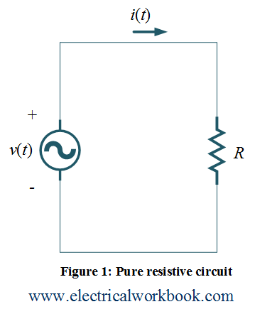
Let us consider a circuit having resitance R supplied by a ac source voltage $v(t)$ as shown in Figure 1 is
$v(t) = {V_m}\sin \omega t$ ….(1)
The current passes throgh resistance R will be
\[i(t) = \frac{{v(t)}}{R} = \frac{{{V_m}}}{R}\sin \omega t = {I_m}\sin \omega t\]
Thus,
$i(t) = {I_m}\sin \omega t$ ….(2)
Phasor Diagram
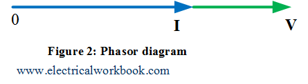
The phasor representation of Equations (1) and (2), is shown in Figure 2, can be written and relate in phasor terms as
\[{\mathbf{I}} = \frac{{\mathbf{V}}}{R}\]
or,
\[{\mathbf{V}} = {\mathbf{I}}R\]
Equations (1) and (2) shows that both current and voltage are in phase so waveforms will look as shown in Figure 3.
Power calculation
The instantaneous power $p(t)$ is defined by the product of instantaneous voltage $v(t)$ and instantaneous current $i(t)$.
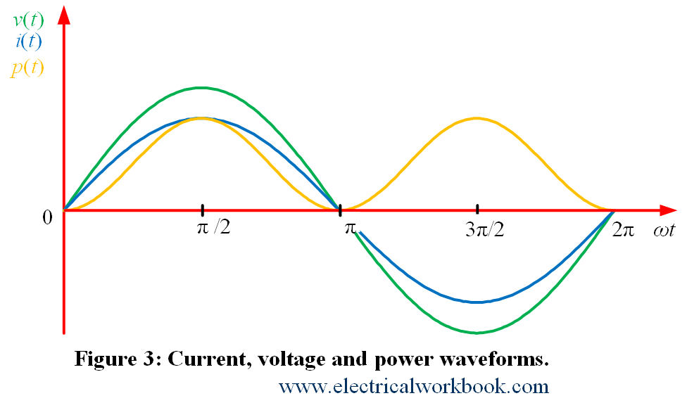
The instantaneous power waveform as shown in Figure 3. And according to the definition, instantaneous power $p(t)$ write as
$p(t) = v(t)i(t)$ ….(3)
Using Equation (3), the average power is defined as
\[{P_{av}} = \frac{1}{T}\int\limits_0^T {p(t)dt} \]
Also,
\[{P_{av}} = \frac{1}{T}\int\limits_0^T {v(t)i(t)dt} \]
\[ = \frac{1}{T}\int\limits_0^T {\left( {{V_m}\sin \omega t} \right)\left( {{I_m}\sin \omega t} \right)dt} \]
\[ = \frac{{{V_m}{I_m}}}{T}\int\limits_0^T {{{\sin }^2}\omega tdt} \]
\[ = \frac{{{V_m}{I_m}}}{{2T}}\int\limits_0^T {\left( {1 – \cos 2\omega t} \right)dt} \]
\[ = \frac{{{V_m}{I_m}}}{2}\]
\[ = \frac{{{V_m}}}{{\sqrt 2 }}\frac{{{I_m}}}{{\sqrt 2 }}\]
\[ = {V_{rms}}{I_{rms}}\]
Thus,
\[{P_{av}} = {V_{rms}}{I_{rms}}.\]
Also, Figure 3 shows that the frequency of instantaneous power ${f_p}$ is twice the frequency of instantaneous voltage ${f_v}$ or the frequency of instantaneous current ${f_i}$ as
\[{f_p} = 2{f_i}{\text{ }}or{\text{ }}2{f_v}\]